FX-DIS Local Controller Display Technical Bulletin6
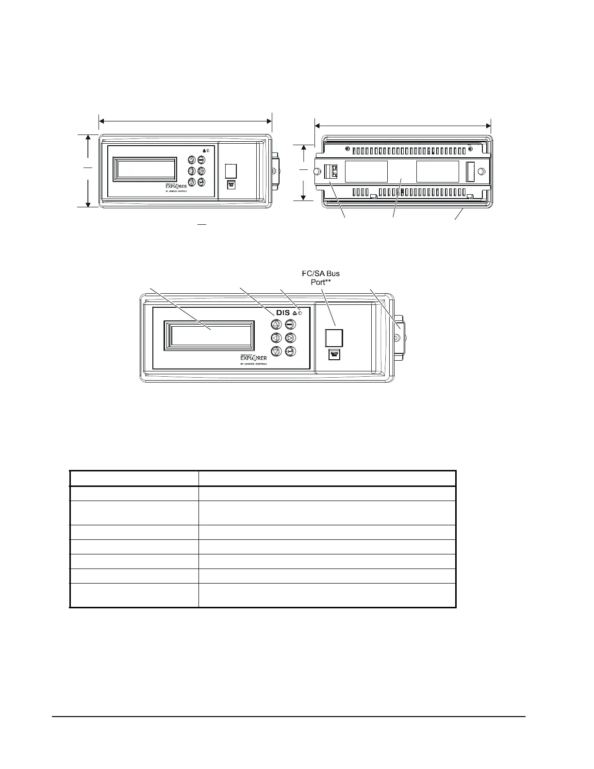
Figure 2 shows the dimensions, and Figure 3 shows the physical features of the
Local Controller Display. The same general design features also to apply FX
controller models that have a built-in display.
Table 2 describes the purpose of each component on the Local Controller Display.
Table 2: Local Controller Display Components
Component Description
Display Screen Displays the controller’s user interface.
FC/SA Bus Port Allows for Bluetooth RJ-12 6-pin device connection for
commissioning purposes.
Keypad Used for interacting with the display.
Red Alarm LED Not used.
Removable Back Plate Used to hold the display onto the door of the enclosure.
Removable O-Ring Fits inside gland around housing perimeter.
SA Bus Access Hole Cutout section on the removable back plate through which the
SA Bus connector cable can pass for connection to the display.
Figure 2: Local Controller Display Dimensions, mm/in.
Removable
O-Ring
Front View
Back View
DIS
Removable
Back Plate
SA Bus
86
3-3/8
231
9-1/16
238
9-3/8
Depth
26
1.0
64
2-1/2
Figure 3: Local Controller Display Physical Features
** RJ-12 6-pin modular jack. To use port, remove cap plug. When done, replace cap plug.
FX_FIG:DIS_LEDs_5.0
Display
Screen
Keypad
Red Alarm
LED*
Removable
Back Plate
* Alarm Light Emitting Diode (LED) not used.
 Loading...