readings during communication pauses. For acceptable Idle Bus Voltage ranges, see
Voltage Levels and the Voltage Table .
It is possible and normal for there to be minor voltage fluctuations while
reading Idle Bus Voltages.
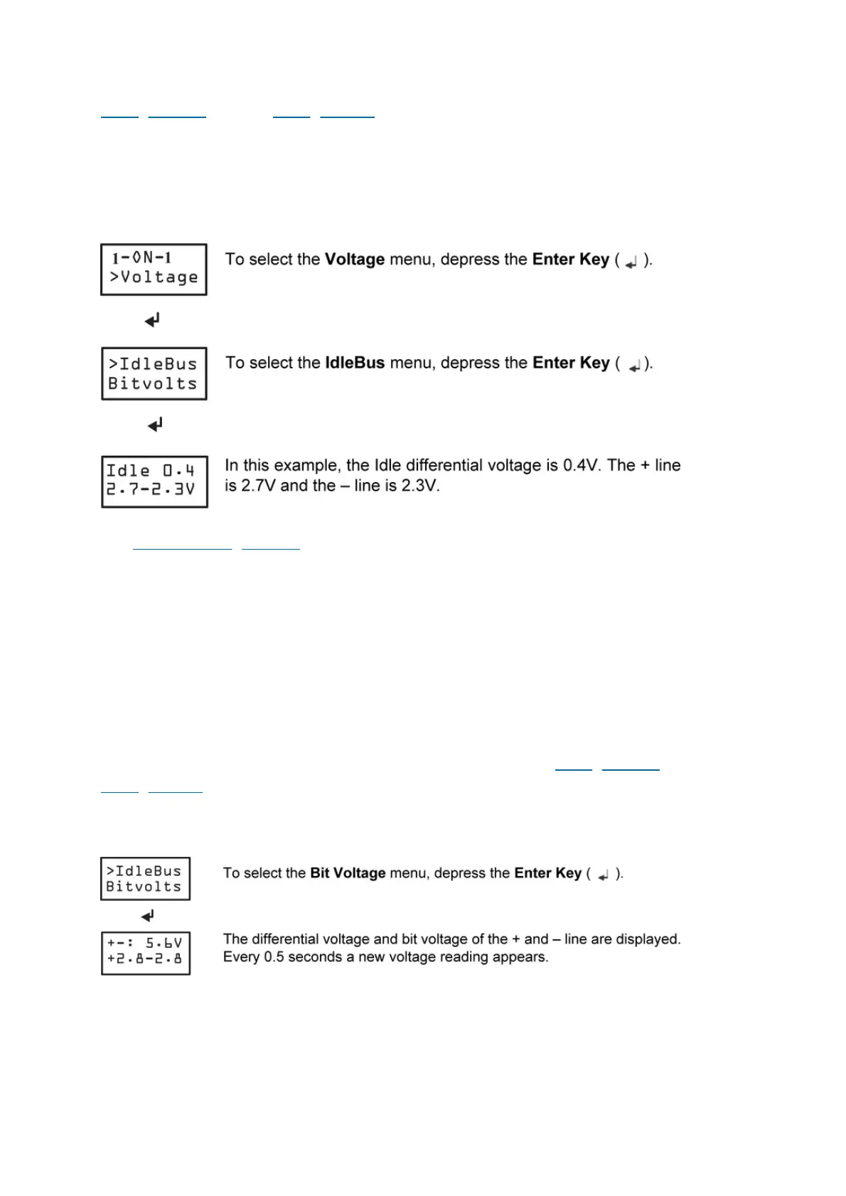
Figure 1. Idle Bus Menu
See Idle Bus Voltage Levels for more information.
Bit Voltage Menu
The Bit Voltage menu displays in real time the voltage when communication is
occurring on the bus. The differential voltage and bit voltage (+, – line with respect to
COM) from a controller are shown on the display. Approximately every half second, a
new voltage sample is taken from the bus and displayed. The voltage sample could
be from any controller on the bus that is communicating at the time of the sample.
Use the Bit Voltage mode for a quick look at the quality of the communications
occurring on the bus. For acceptable Bit Voltage ranges, see Voltage Levels and the
Voltage Table .
Figure 1. Bit Voltage Menu
Meter Menu
The Meter menu turns the display into a voltmeter that is measuring the current
voltage seen on the bus. This mode can be used to look at voltage bias levels or to
Note:
 Loading...