in the range of 4–10 VDC differential voltage and 2 to 5 VDC for the +, – line
voltages. The important thing to note is that the + and – line readings typically are
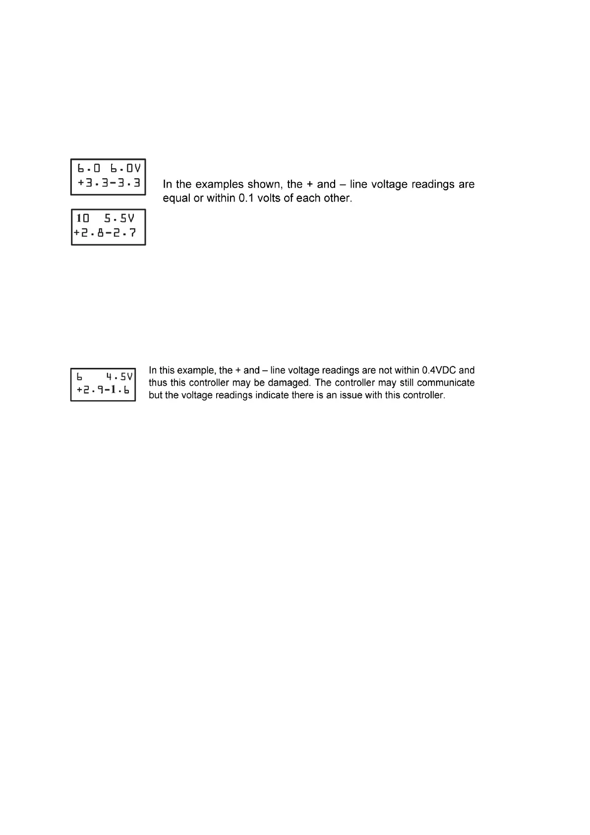
equal or within approximately 0.2VDC of each other. The + line voltage will usually
read equal to or slightly higher than the – line voltage. See Figure 21 for an example.
Figure 1. 1-ON-1 Communication Example 1
If the readings taken are below 4V differential or the + and – readings are not within
0.4VDC of each other, then the controller may be damaged. Damaged controllers
typically have a larger voltage difference (greater than 0.4VDC) between + and -
readings. See Figure 22 for an example.
Figure 2. 1-ON-1 Communication Example 2
Network Communication Voltage Levels
When the FIT is connected to a network of controllers it will measure the
communication voltage levels of each individual controller. When looking at
communication voltage levels on a network, it is important to note that the voltage
levels are affected by many factors, such as wire length, wire gauge, number of
controllers, network topology, EOL terminations, and the FIT connection on the bus.
The FIT’s connection location affects the voltage readings taken. The controllers
closer to the FIT typically have higher voltage readings than the controllers farther
away from the FIT. It is therefore important to take note of the network location
where the FIT is connected since the voltage readings are affected.
Differential voltage levels in the range of (2.5V to 8V) are expected on most properly
functioning buses. The + line voltage and – voltage should be approximately equal or
within 0.2VDC of each other on a properly wired and terminated bus.
Since the FIT is reading and calculating these voltages, they are only accurate for the
bus segment to which the FIT is connected. If using communication voltages to
troubleshoot, each bus segment should be read independently. Voltage readings
where there are large voltage differences between the + line and – line can indicate a
wiring problem such as a shorted, pinched, or open wire connection.
Voltage Table
 Loading...