The FIT can measure the voltage levels on the RS-485 MS/TP communications on the
FC/SA bus. The RS-485 communications produce a differential voltage between the +
and – communication wires. The differential voltage is the addition of the + wire
voltage with respect to the COM wire and the – wire voltage with respect to the COM
wire. The FIT will measure the (+, COM) voltage and the (–, COM) voltage, and the
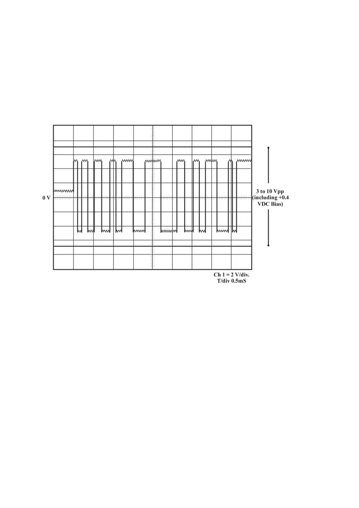
sum of these voltages is the differential voltage. If you view the differential voltage of
a RS-485 communication on an oscilloscope, it resembles Figure 17.
Figure 1. Communication Voltage Example
The waveform is uniform above and below the 0 V line which represents
the COM line. The bus EOL termination provides approximately 0.4 VDC of bias
voltage to keep the bus in the high state when communications are idle. The EOL
also provides proper bus termination.
When reading an FC Bus with multiple controllers, this Communication Voltage is the
reading displayed by the FIT during the Monitor or Scan modes. It can also be
displayed though the Voltage menu in submenu item BitVolts, but the reading
displayed through the Voltage menu is from the controller on the bus that is
communicating at the time of the sample was read when no address is provided by
the FIT. Ideally, the + to COM and – to com readings should have an absolute value
almost equal and no more than approximately 0.2 VDC apart. When the two readings
have an absolute value greater than approximately 0.2 VDC difference, it could mean
there is a loose connection on the bus cable at the controller, some other cable
problem near the address displayed, or a problem with the controller itself.
Idle Bus Voltage Levels
Note:
 Loading...