With proper EOL termination, the idle bus voltage should read approximately 2.7–2.3
VDC or 0.4V DC differential. The + communication line is biased at 2.7 VDC with
respect to the COM line and the—communication line is biased at 2.3 VDC with
respect to the COM line. The idle bus voltage can vary with wire length and bus
loading but should not be lower than approximately 0.2 VDC differential or higher
than approximately 0.9 VDC differential.
It is also possible to read minor voltage fluctuations while reading the idle
bus voltage. These minor changes are normal.
Reading the idle bus voltage is a good way to find common wiring mistakes. If you
discover that the MS/TP voltages are outside the recommended ranges, see Table 6
for guidelines and possible solutions.
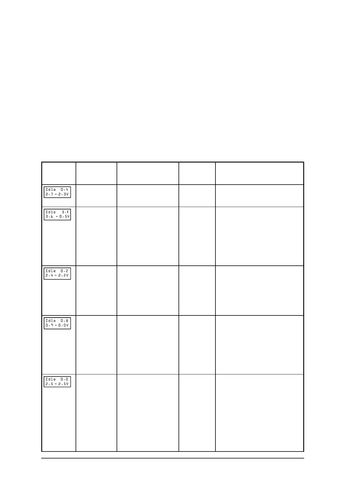
Table 1. Using Voltages and Issues to Troubleshoot
FIT
Display
Installation
Problem
Idle Bus Voltage
Symptom
FIT Issues
Menu Resolution Process
None None None FIT is showing a correct
reading
Missing all
EOLs, Cut
Cables
Reading value
greater than 3
VDC.
2
nd
Token
Look at as-built drawings.
Check EOLs. Use FIT to
look for quantity of devices
on bus. Check each
controller’s EOL switch
using the FIT.
EOL(s) ON
but no
power at
controller
+ to - reading
drops too low and
other readings are
dropping low in
their range.
None Look for quantity of
devices on bus. Check each
controller EOL switch using
the FIT.
- and COM
are
swapped.
+ to COM and - to
COM drops with
the - to COM
reading
attempting to go
to near 0 VDC.
CHRFrame
BadFrame
OutOfSeq
Controllers near the
problem are not reporting.
Look for missing
addresses.
+ and - are
swapped
The + to - reading
is trying to go to 0
VDC and the + to
COM and - to
COM is trying to
equalize including
all readings
resulting at 0 VDC.
ChrFrame Zero or few controller
addresses are
reporting.Split the bus in
half and test each segment
individually. Continue this
process with smaller
segments until the issue is
found.
Note:
 Loading...