Note: Use the RS-232 adapter described in this
section if you are replacing an NAE with an SNE
model, and you used the M-Bus Level Converter for
integrating the M-Bus network to the NAE's RS-232
port. The RS-232 adapter requires an external power
supply as it does not receive power from the USB
connection.
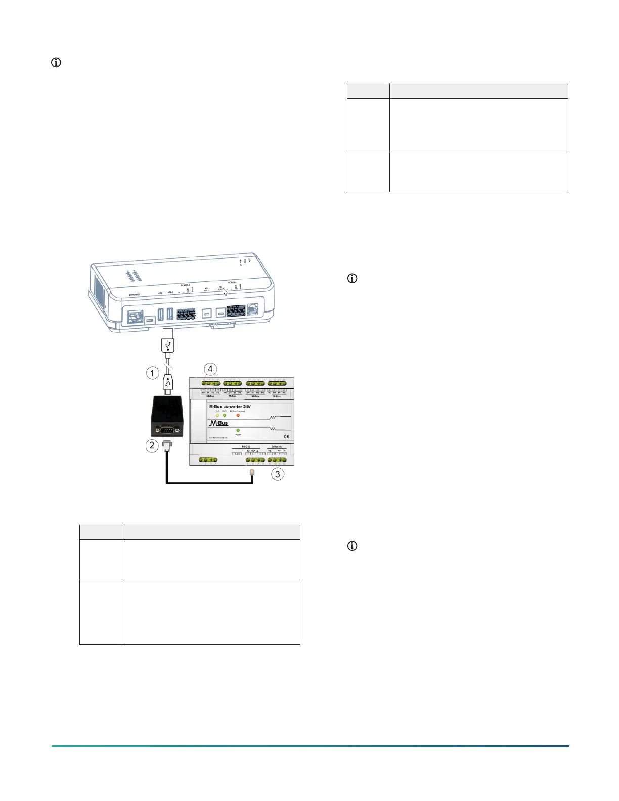
1. Connect the USB cable from the SNE to the RS-232
adapter. You can use either USB-1 or USB-2 port on
the SNE.
2. Connect the RS-232 cable from the RS-232 adapter
to the RS-232 connection on the M-Bus Level
Converter using cable INT-DX-KAB01. Wire to
terminals GND, RxD, and TxD.
Figure 11: Connecting SNE to M-Bus Network using
serial M-Bus Level Converter
Table 11: M-Bus Level Converter connection
detail
Callout Description
1 USB connection:
Connect USB cable from SNE to RS-232
converter
2 RS-232 wire connection (serial cable INT-DX-
KAB01):
5: TxD (transmit data); PIN 2 on RJ12
6: RxD (receive data); PIN 3 on RJ12
7: GND (ground); PIN 5 on RJ12
Table 11: M-Bus Level Converter connection
detail
Callout Description
3 Power connections (24 VAC/DC):
9: PE
11: 24+ V/~
12: 24- V/~
4 M-Bus connections:
13: M+
14: M-
3. Wire from the M+ and M- terminals on the level
converter to the M-Bus meters using a free
topology (star, tree, or line). See Figure 11 for an
example. Specific cabling can vary depending on
the topology and site. See Wiring considerations
and guidelines for network integrations.
Note: If the number of M-Bus unit loads or
distances exceeds the specifications of a level
converter, an M-Bus repeater can be wired to
the converter to increase the number of unit
loads and distances. The converter shown in
Figure 11 is capable of handling up to 100 unit
loads. See SNE ordering information for a list
of M-Bus devices.
4. Connect the 24 VAC supply power wires from the
transformer to the -/~ and +/~ terminals as shown
in Figure 11, but do not supply power to the unit
until after you supply power to the network engine.
5. Go to Connecting the power source.
Connecting KNX devices
About this task:
The SNE connects to a KNX network device by using the
KNX/IP interface router. (After installation and wiring are
complete, refer to the Network Engine Commissioning for
KNX Vendor Integration Application Note (LIT-12013148) for
additional information.)
1. Connect an Ethernet cable to the port on the front
of the KNX gateway as shown in Figure 12.
Note: Depending on the size of your network,
you can use either a KNX Interface or Router
as a gateway. The Interface connects the
network engine to a single KNX line, while the
Router acts as both an Interface and a Line
Coupler over Ethernet to connect the network
engine to the network, not to a single device.
SNE Installation Guide10
 Loading...


