connections that sets the engine as a network terminated
device on the bus.
To set a network engine as an FC Bus terminated device,
position the switch on the EOL switch block to the ON
position as shown in Figure 14.
Figure 14: FC Bus EOL switch in the factory default ON
(Up) position
Note: The network engine is shipped with each EOL
switch in the initial factory position, ON as shown in
Figure 14. If the network engine is not a terminated
device on the FC Bus, reposition the switch on the
EOL switch block to the Off (down) position.
Set the EOL switches appropriately for FC Bus-1 and, if
present, FC Bus-2. The network engine follows the same
rules as other switch-terminating devices listed in the
Setting Terminations section of the MS/TP Communications
Bus Technical Bulletin (LIT-12011034).
For the RS-485 connection, set the EOL termination to
ON (or install an EOL terminator) for the two devices
located at either end of each bus segment on an RS-485
bus. Set the EOL switches to off (or do not install an EOL
terminator) for all other devices on the bus segment on
an RS-485 bus.
Powering on the Network Engine
Apply power to the network engine. After applying power,
the device requires approximately three minutes to start
up and become operational. See LED test sequence at
startup.
Startup is complete and the network engine is operational
when the HEARTBEAT LED is flashing purple and the
FAULT LED is Off. The various LEDs are shown in Figure 15.
Disconnecting power from the Network
Engine
Disconnect power from the network engine by removing
the terminal block plug from the power terminal port
on the network engine (Figure 13) or disconnecting the
power adapter cable.
When you disconnect or lose supply power from
the network engine, the network engine becomes
nonoperational when the power management settings
expire. The HEARTBEAT LED (Figure 15) remains On (blue),
and the super capacitor continues to power the network
engine for approximately 30 seconds so that volatile data
can be backed up in nonvolatile memory. The HEARTBEAT
LED goes Off when the data backup is completed.
Note: The behavior of the super capacitor is
different from backup batteries that network
engines have used in the past. For example, the
capacitor requires time to recharge after each power
cycle. The unit is not designed for frequent power
cycles over a short period of time, such as three or
four power cycles in one hour. In this scenario, the
capacitor can deplete enough so that it no longer
functions. A fully depleted capacitor can take up to
90 minutes to recharge after the network engine is
plugged into its power source.
Troubleshooting
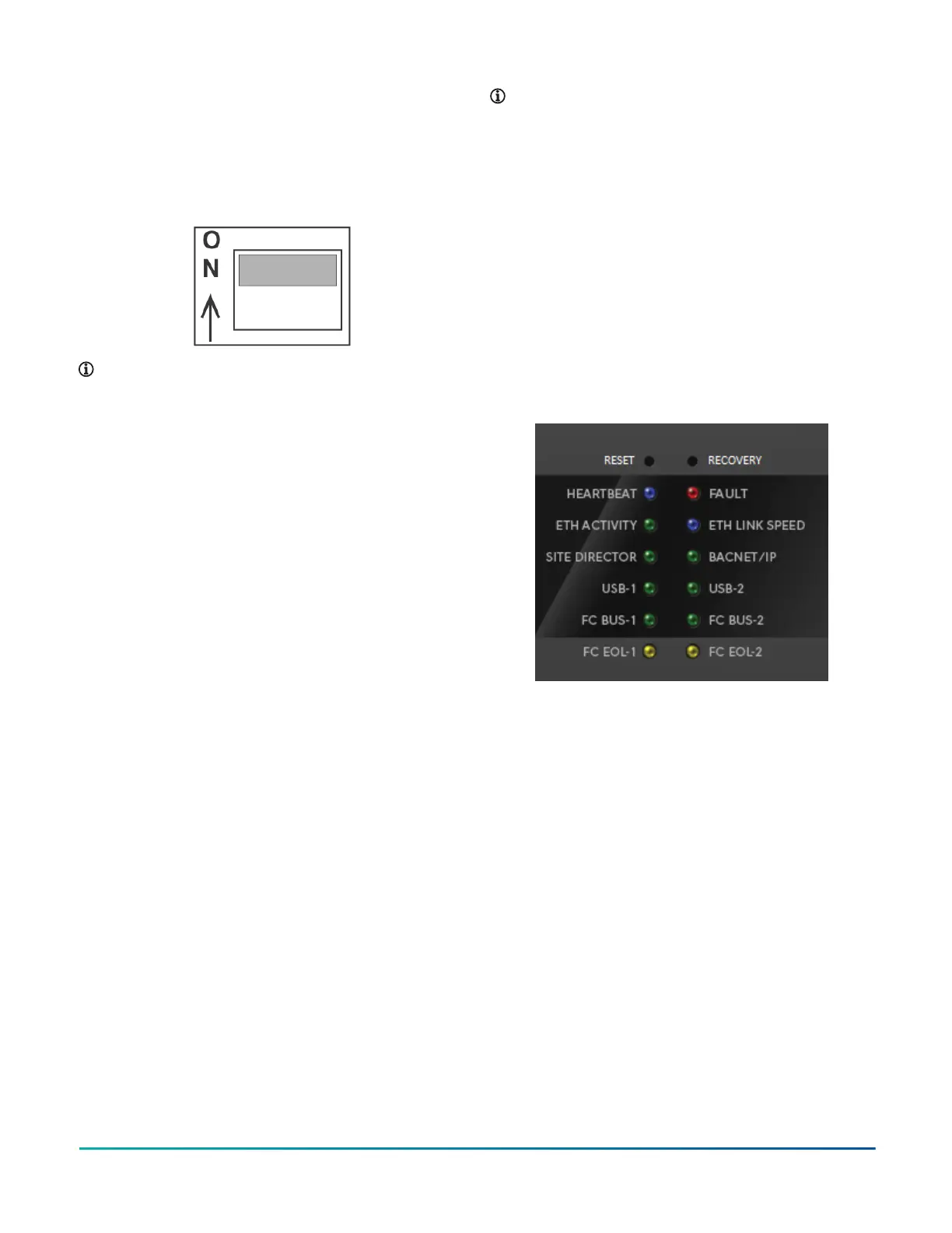
LED status indicators
LEDs on the front panel of the SNE indicate its functional
state. For a comprehensive list of LED functional
information, see Figure 15 and Table 13.
Figure 15: Network Engine with LED designations
LED test sequence at startup
During startup, the network engine automatically
initiates a self-test to verify proper operation of the unit.
Immediately after connecting supply power, the following
LED lighting sequence occurs:
• The HEARTBEAT LED flashes blue/purple when the
network engine starts.
• The FAULT LED is solid red for approximately 30
seconds, then turns off.
• The USB-1 and USB-2 LEDs flash green when a
supported device is connected to the respective USB
port. The LEDs turn solid red when an unsupported
device is connected. The LEDs are off if no device is
connected.
SNE LED indication table
The following table describes the meanings of each LED
on the SNE. The normal states are in bold. A flicker has a
fast blink rate (faster than one second) whereas a flash
has a much slower blink rate (one second or more).
SNE Installation Guide12
 Loading...


