2. Defaults the engine's hostname to SNE and MAC
address.
3. Defaults the IP address to DHCP.
4. Reverts to the factory default security database.
5. Runs on the opposite partition, possible with a
different installed release.
Recovery is complete when the Heartbeat LED starts
to blink at 1 second.
Note: To determine which partition is currently
active, open the Metasys SMP UI in Expert
mode and locate the Update object of the SNE
under All items > Expert. The Active System
Partition attribute is visible under the Focus
window of the Update object. Partition 0 is A
and partition 1 is B.
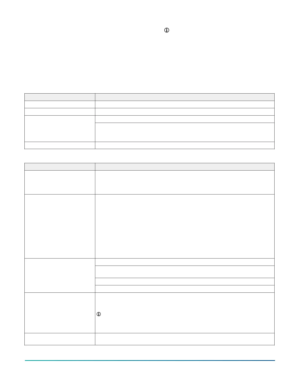
Wiring considerations and guidelines
Table 14: SNE Ethernet network rules
Category Rules/maximums allowed
General Star topology with network switches
Number of devices Maximum of 1,000 network engines at one site in the Metasys network.
2,000 m (6,600 ft) for plastic/glass fiber optic with external adapterLine length and type
1000 BaseT: 100 m (330 ft) Cat5E or Cat6 cable
100 BaseT: 100 m (330 ft) Cat5 or Cat6 cable
10 BaseT: 100 m (330 ft) Cat5 or Cat6 cable
Terminations For 1000/100/10 BaseT, no line terminators allowed.
Table 15: Guidelines for BACnet protocol MS/TP network topology
Category Rules/maximums allowed
General SNE2200x model supports two BACnet MS/TP field controller (FC) trunks
SNE1100x, SNE110Lx, and SNE1050x models support one BACnet MS/TP field
controller (FC) trunk
Field controller trunks are wired with a daisy chain topology only.
Number of devices SNE2200x model: 200 devices per Field Controller (FC) Bus with no more than two
repeaters between the network engine and any device and a maximum of 50 devices
between repeaters; two FC Buses
SNE110Lx models: 100 devices per Field Controller (FC) Bus with no more than two
repeaters between the network engine and any device and a maximum of 50 devices
between repeaters; one FC Bus
SNE1100x models: 100 devices per Field Controller (FC) Bus with no more than two
repeaters between the network engine and any device and a maximum of 50 devices
between repeaters; one FC Bus model does not support the N2 Bus trunk.
SNE1050x model: 50 devices per Field Controller (FC) Bus with no more than two
repeaters between the network engine and any device and a maximum of 50 devices
between repeaters; one FC Bus
1,500 m (5,000 ft) cable without a repeater
4,500 m (15,000 ft) cable from the network engine to the farthest FC Bus device (three
bus segments of 1,500 m [5,000 ft] each, separated by repeaters)
2,000 m (6,600 ft) between two fiber modems
Line length and type
Use a 6 mm (0.250 in.) wire strip
Cable type Stranded 0.6 mm (22 AWG) 3-wire twisted, shielded cable is recommended.
Stranded 0.6 mm (22 AWG) shielded 4-wire (two twisted-pairs) shielded cable is
acceptable.
Note: The + and - bus leads should be a twisted pair. On applications using 4-
wire (two twisted-pairs) cable, isolate and insulate unused conductor. Refer to
the MS/TP Communications Bus Technical Bulletin (LIT-12011034) for more infor-
mation.
Terminations Two FC devices with end-of-line (EOL) switches in the ON position, one at each end of
each FC Bus segment
SNE Installation Guide 15
 Loading...


