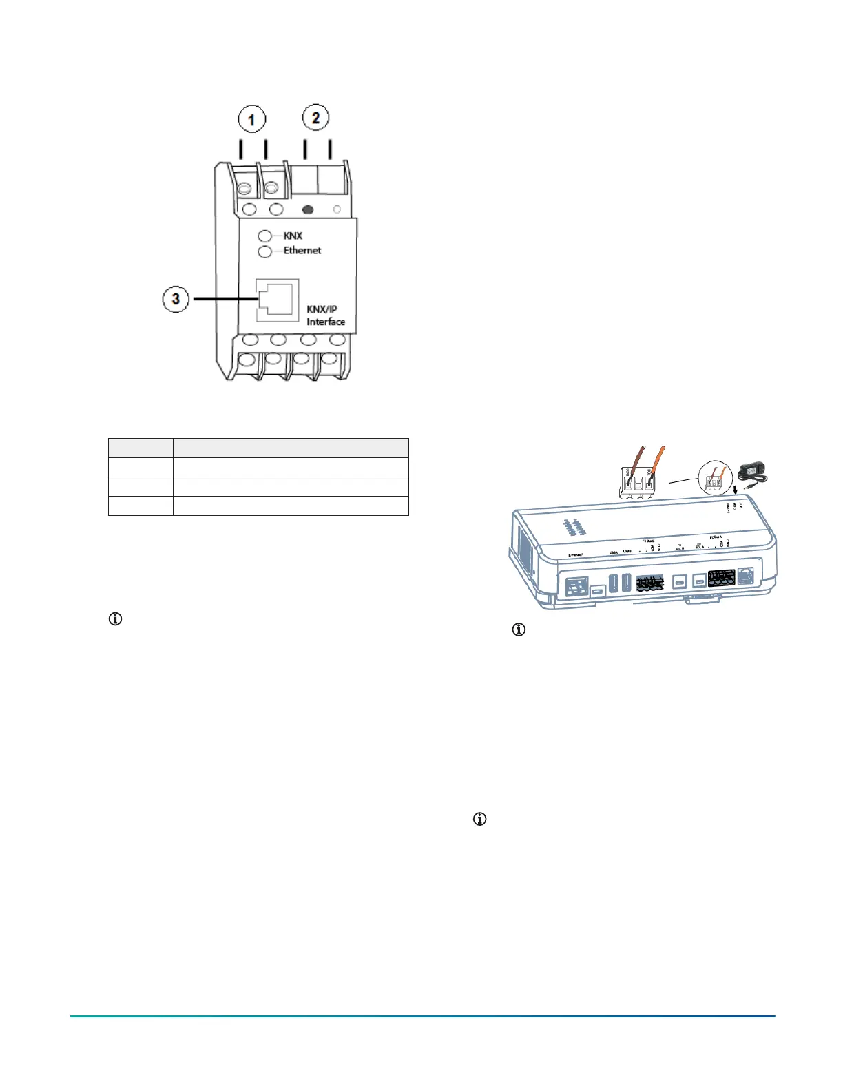
Figure 12: KNX/IP Interface Router
Table 12: KNX/IP Interface Router connection
detail
Callout Description
1 To power supply
2 To KNX devices
3 To Ethernet network
2. For a single KNX line, wire from the red and black
terminals on the gateway to the devices. For
multiple KNX lines, wire from the red and black
terminals on each gateway to the devices on the
same KNX line.
Note: Specific cabling can vary depending
on the topology and site. See Wiring
considerations and guidelines for network
integrations.
3. Wire each KNX gateway to its own dedicated power
supply on the KNX line. Do not supply power to
the gateway until after you turn on the network
engine.
4. Go to Connecting the power source.
Connecting other third-party devices
About this task:
The SNE supports several other third-party devices. Refer
to the following documents for information on how to
connect the network engine to these devices:
• C•CURE-victor: Network Engine Commissioning for
C•CURE-victor Integration Application Note (LIT-12013151)
• Simplex FACU: Network Engine Commissioning for
Simplex Fire System Integration (LIT-12013060)
• Cree SmartCast Lighting Control: Metasys System
Commissioning for Cree Digital Lighting Systems
Integration (LIT-12013152)
• Molex Lighting Control: Metasys System Commissioning
for Molex Digital Lighting Systems Integration
(LIT-12013153)
• Zettler Fire Panel: Network Engine Commissioning for
Zettler MX Speak 6.0 Vendor Integration (LIT-12013269)
• OPC UA Servers: Network Engine Commissioning for OPC
UA Client Vendor Integration (LIT-12013545)
Connecting the power source
About this task:
To terminate the power connection to the network
engine, complete the following steps:
1. Connect power to the network engine according to
the power source you are using:
a. If you are using a 24 VAC power transformer,
connect the 24 VAC supply power wires from
the transformer to the removable power
terminal block plug on the network engine
(Figure 13). The connections are HOT and
COM (common). Insert the plug.
Figure 13: Supply Power Wiring (24 VAC Transformer or
24 VDC Adapter)
Note: Power supply wire colors may
be different on transformers not
manufactured by Johnson Controls.
Follow the transformer manufacturer’s
instructions and the project installation
drawings.
b. If you are using the 24 VDC power adapter,
plug the power adapter into the round 24
VDC barrel plug located in the upper right
corner of the network engine. See Figure 13.
Connect the 24 VDC power adapter to 120
VAC.
Note: Do not use both the power terminal
block and the power adapter; select either
one.
2. Go to Setting end-of-line switches.
Setup and adjustments
Setting end-of-line switches
The network devices at each end of an FC Bus segment
must be set as network terminated devices. The network
engine has one EOL switch for each of its FC Bus
SNE Installation Guide 11