protocol. The FC bus port pin assignment is shown in the
following figure.
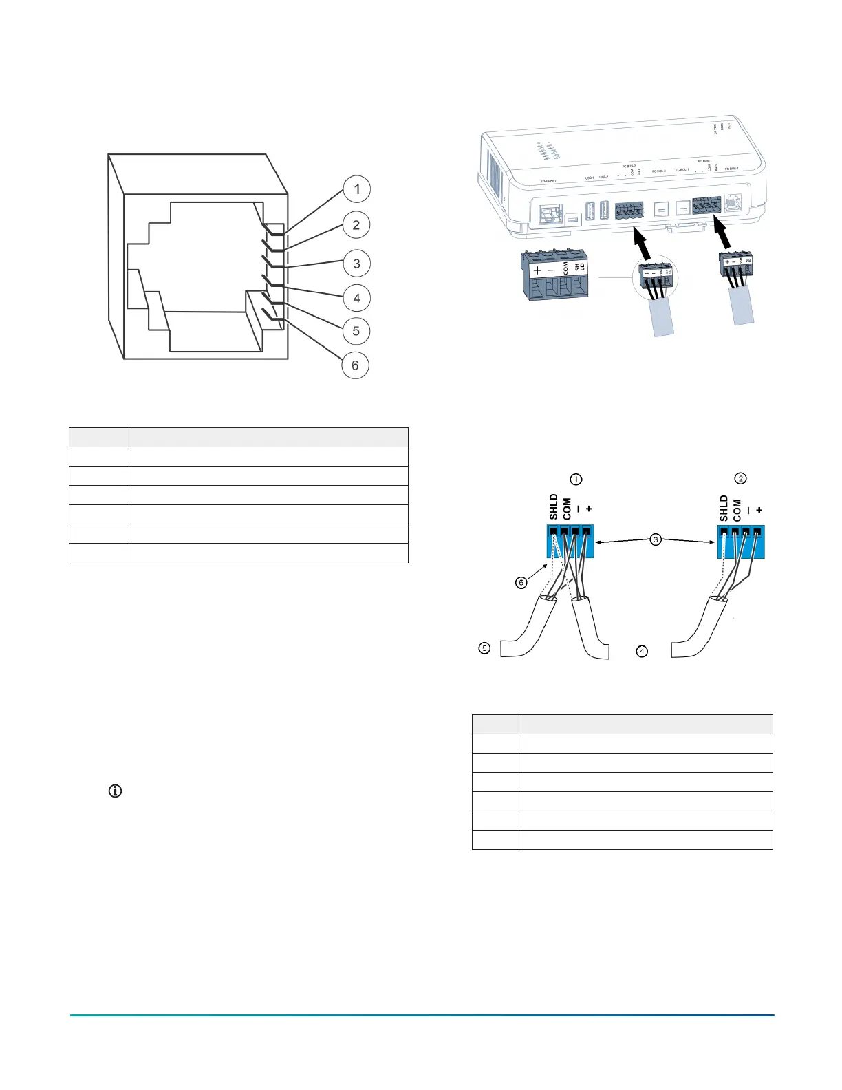
Figure 4: Pin number assignments for FC Bus port on
SNE
Table 6: Pin number assignments for FC Bus port on
SNE (RJ-12 modular jack)
Callout Signal
1 FC Bus (+)
2 FC Bus (-)
3 Bus and Power Common
4 Power (15 VDC)
5 Bus and Power Common
6 Power (15 VDC)
Connecting MS/TP and N2 bus devices
About this task:
Supported field bus integrations include BACnet MS/TP
and N2 Bus. The SNE1100x, SNE110Lx, and SNE1050x
models have one field bus connection each and the
SNE2200x model has two field bus connections. All models
also include an RJ-12 FC Bus connection.
1. Connect the 3-wire bus cable to the removable 4-
terminal plugs labeled FC BUS-1 or FC BUS-2 as
shown in Figure 5. If you have the SNE2200x with
two integrations, use FC BUS-1 for one network and
FC BUS-2 for the other.
Note: The FC Bus terminal blocks on the SNE
are blue.
Figure 5: FC Bus terminal blocks and wiring
connections (SNE22000 shown)
2. Set the FC EOL-1 and FC EOL-2 switches to the
proper positions. See Setting end-of-line switches.
3. To add additional field devices, wire from one
device to the next in a daisy-chained fashion as
shown below. Do not connect more than two wires
to each terminal.
Figure 6: Field bus wiring detail: daisy chained devices
Table 7: FC Bus terminal block wiring
Callout Description
1 Daisy-chained device on FC Bus segment
2 Terminating device on FC Bus segment
3 FC Bus terminal plugs
4 To next device on FC Bus segment
5 From previous device on FC Bus segment
6 Isolated shield connection terminal
4. Go to Connecting the power source.
Connecting LonWorks devices
About this task:
The SNE connects to LonWorks network devices by using a
USB to LON adapter (code number ACC-USBLON-0) that is
SNE Installation Guide 7