Important: Utiliser ce SNE uniquement en tant
que dispositif de contrôle de fonctionnement.
Lorsqu'une défaillance ou un dysfonctionnement
du SNE risque de provoquer des blessures ou
d'endommager l'équipement contrôlé ou un
autre équipement, la conception du système de
contrôle doit intégrer des dispositifs de protection
supplémentaires. Veiller dans ce cas à intégrer de
façon permanente d'autres dispositifs, tels que
des systèmes de supervision ou d'alarme, ou des
dispositifs de sécurité ou de limitation, ayant une
fonction d'avertissement ou de protection en cas de
défaillance ou de dysfonctionnement du SNE.
Important:
• Do not apply power to the network engine before
you complete and check connections. Short
circuits or improperly connected wires may result
in permanent damage to the equipment.
• Use copper conductors only. Make all wiring in
accordance with local, national, and regional
regulations.
• The network engine is a low-voltage device. Do
not exceed the network engine electrical ratings.
Applying high voltage to the network engine will
void any warranties and may result in permanent
damage.
• Do not remove the terminal block keys. The
terminal block plugs and the terminal sockets are
keyed to fit together in the correct configuration
only.
• Prevent any electrostatic discharge (ESD) to
the network engine. Static electric discharge
can damage the network engine and void any
warranties.
Follow these guidelines when wiring the network engine:
• Route the supply power wires and communication
cables at least 50 mm (2 in.) away from the vent slots in
the sides of the network engine housing.
• Provide slack in the wires and cables. Keep cables
routed neatly around the network engine to promote
good ventilation, LED visibility, and ease of service.
• Ensure that the building automation network wiring
meets the specifications, rules, and guidelines in Wiring
considerations and guidelines.
• Follow the transformer manufacturer’s instructions
and the project installation drawings. Power supply
wire colors may be different on transformers not
manufactured by Johnson Controls
®
.
• Verify that transformer phasing is uniform across the
devices. Powering network devices with uniform 24 VAC
supply power phasing reduces noise, interference, and
ground loop problems.
• Do not connect the network engine to an earth ground
connection.
Method for tightening terminal blocks
If you over-torque the terminal block screws during
installation of a Metasys SNC network control engine,
CGM general purpose application controller, or CVM
VAV box controller, the pole gap in the terminal block
may increase and create a loose connection. This can
affect any of the terminal blocks. Torquing the terminal
screws while the terminal blocks are attached to the
pin can damage the contact and can also cause loose
connections.
To prevent over-torquing and damage to the contacts:
Note: It is best practice to remove the connector
block from the pin headers on the unit before wiring
the terminal blocks. The best way to prevent any
contact damage and loose connections is to avoid
torquing the terminal screws while the plugs are
attached to the pin headers.
1. If available, use a torque screwdriver to tighten the
screw to .25 NM (2.212 in. lbs.). The recommended
bit size for the universal screws on the terminal
blocks is a Phillips #1, or a slotted 1/8 in. (3.0mm)
bit.
2. If a torque screwdriver is not available, tighten the
terminal screws until the screw is snug on wire, and
then tighten the screw an additional quarter (90°)
to half (180°) turn.
Note: The design of the terminal block screw
is meant to help prevent over torque. Do not
attempt to tighten by using more down force
than necessary.
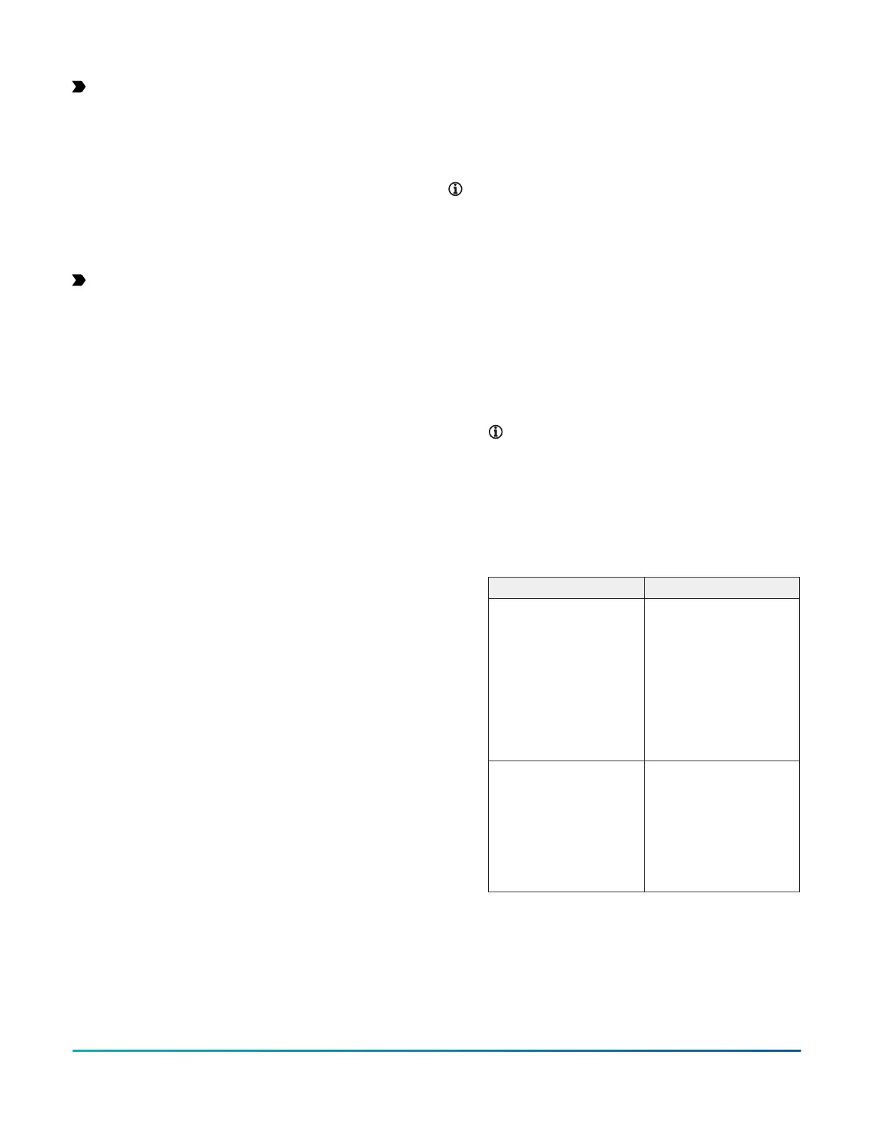
If a terminal block is exhibiting these symptoms,
replace the terminal block. See the following table
for replacement terminal block kits:
Table 5: Terminal block replacement part
numbers
Product Code Number Description
ACC-TBKINOUT-0 Input and Output
terminal block
replacement kit for
SNC, CGM, and CVM
products. Kit includes
5 of each 2, 3, and 4
position Input and
Output terminal blocks.
30 terminal blocks in
total.
ACC-TBKPWFCSA-0 Power, FC Bus, and
SA Bus terminal block
replacement kit for
SNC, CGM, and CVM
products. Kit includes 5
of each terminal block
type. 15 terminal blocks
in total.
Connecting MAP Gateway
The FC Bus port is an RJ-12, 6-position modular jack that
provides a connection for the Mobile Access Portal (MAP)
Gateway.
The FC Bus port is connected internally to the FC Bus
terminal block and so they share only one communication
SNE Installation Guide6