wired between the USB port and the LON network. (After
installation and wiring are complete, refer to the LonWorks
Network Integration with NAE and LCS Technical Bulletin
(LIT-1201668) for additional information.)
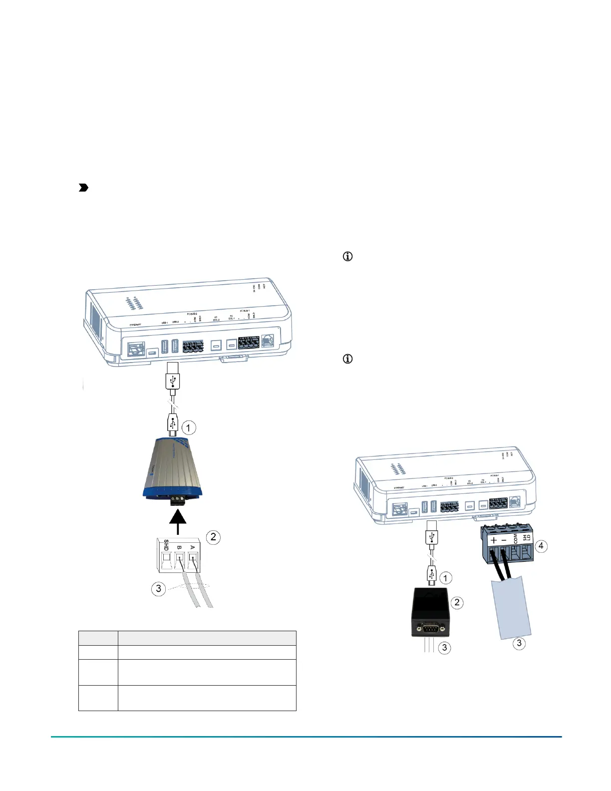
1. Connect the 2-wire cable from the LonWorks
network trunk to the removable 3-pin terminal
block on the USB to LON adapter (code number
ACC-USBLON-0) as shown in Figure 7. The SHD
connection is not used. Connect the USB cable from
the USB adapter to the USB-1 or USB-2 port on the
SNE. You can use either port.
Important: Use only the USB adapters that
were tested and qualified for use with the
SNE. Other non-qualified adapters do not
function in the USB ports of the SNE. See USB
ports for more information.
Figure 7: LonWorks Network terminal block and wiring
connections
Table 8: LonWorks connection detail
Callout Description
1 USB connection (to USB-1 or USB-2)
2 LonWorks terminal block; wires are not
polarity sensitive
3 Optional shield; connect shields together and
insulate with tape
2. Go to Connecting the power source.
Connecting Modbus RTU devices
About this task:
The SNE connects to Modbus RTU devices directly if the
RS-485 protocol is in use or by using an USB to RS-232
adapter if the RS-232 protocol is in use. After installation
and wiring are complete, refer to the Network Engine
Commissioning for Modbus Vendor Integration Application
Note (LIT-12013150) for additional information.
1. For a Modbus RTU protocol that requires an RS-485
serial connection, connect the 2-wire bus cable to
the removable 4-terminal plug labeled FC BUS-1 as
shown in Figure 8. If you have the SNE2200x model,
you can otherwise use the second terminal plug
that is identical in function and labeled FC BUS-2.
The RS-485 bus is a two-wire network.
Note: When the FC BUS-1 connection is used
for Modbus integration, it is not available for
BACnet Field Controllers or the MAP.
2. For a Modbus RTU protocol that requires an
RS-232C B serial connection, use the USB to RS-232
adapter, code number ACC-USBRS232-0. Connect
the three wires from a USB-to-RS-232 serial port
converter on the SNE to the RS-232 adapter. Plug
the USB adapter into USB-1 or USB-2 converter.
Note: The maximum cable length between
devices connected though an RS-232 line
depends on the baud rate used. For example,
if the device communicates at 9600 baud, do
not exceed a cable length of 15 meters.
Figure 8: FC Bus terminal connection for Modbus
devices (both Modbus connection types shown)
SNE Installation Guide8