Materials and special tools needed
You can mount the SNE by using the fasteners option or
the DIN rail option.
• Fasteners option - Three fasteners appropriate for the
mounting surface:
- #8 screws - North America
- M4 screws - Europe
• DIN rail option - 19.0 cm (7.5 in.) or longer section of 35
mm (1 1/8 in.) for DIN rail mount applications only.
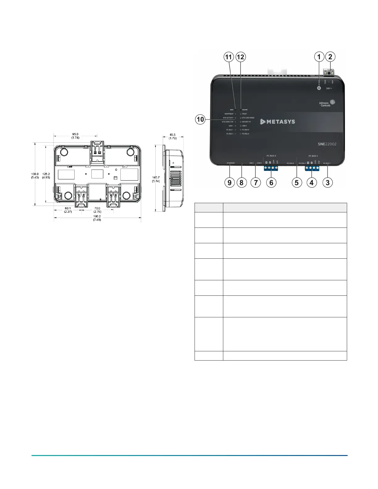
Dimensions
Figure 1: SNE dimensions, mm (in.)
Physical features
The following figure shows the physical features of the
four SNE models available. The total field controller (FC)
device count for each model is as follows:
• SNE2200x: 2 FC Bus trunks; up to 200 devices on FC Bus
trunks
• SNE1100x: 1 FC Bus trunk; up to 100 devices on FC Bus
trunks
• SNE1050x: 1 FC Bus trunk; up to 50 devices on FC Bus
trunks
• SNE110Lx: 1 FC Bus trunk; up to 100 devices on FC Bus
trunks; available in select regions of Australia, China,
Hong Kong, India, Indonesia, Japan, Korea, Malaysia,
New Zealand, Philippines, Singapore, Taiwan, Thailand,
Vietnam, and select branches
The accompanying table provides a description of the
physical features and a reference to further information
where relevant. Also, not all ports and connections are
available for every model. See SNE ordering information
for a list of features available on each network engine.
Figure 2: Physical Features of SNE models (SNE22002
shown)
Table 2: Physical features of the SNE
Callout Physical features
1 Supply power adapter connection: 24 VDC
barrel jack. See Power supply.
2 Supply power removable terminal block: gray
terminals; 24 VAC, Class 2. See Power supply.
3 FC Bus port: RJ-12 6-pin Modular Jack. See
Connecting MAP Gateway.
4 FC Bus removable terminal block for FC
BUS-1: blue terminal. See FC Bus terminal
blocks.
5 End-of-Line (EOL) switches for FC BUS-1 and
FC BUS-2. See Setting end-of-line switches.
6 FC Bus removable terminal block for FC
BUS-2: blue terminal. Only present on
SNE2200x model. See FC Bus terminal blocks.
7 Two Universal Serial Bus (USB) 2.0 host type
A ports. The USB-1 port can use any Johnson
Controls approved USB device; USB-2 port
can use any non-wireless, Johnson Controls
approved USB device. See USB ports.
8 Micro-USB port (not functional)
SNE Installation Guide2