UNT Controller—Unitary (UNT) Controller
21
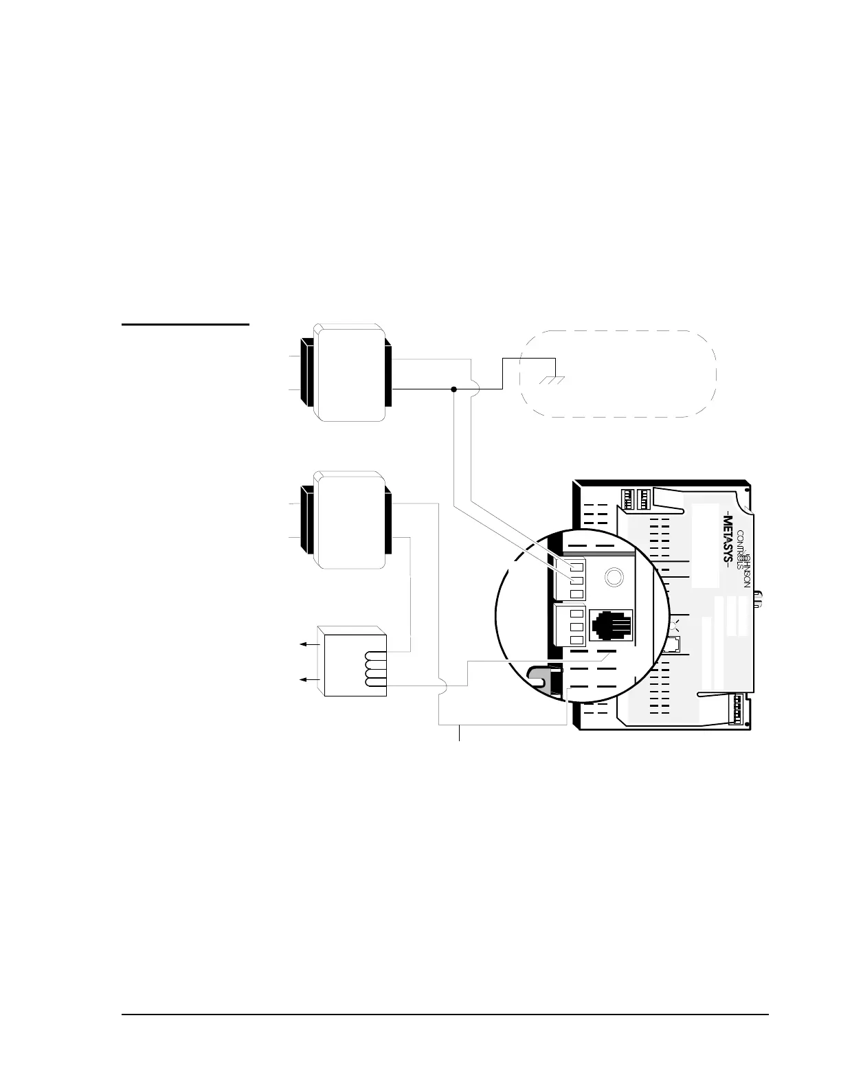
24 VAC to 24 VAC isolation transformers for UNT110/111,
UNT120/121, and UNT140/141 series controllers are not mandatory.
UNT110/111, UNT120/121, and UNT140/141 series controllers do not
require an isolation relay. However, you must connect the jumper wire
from the triac terminal to 24 VAC if the contact or coil loads are grounded
(via the single earth ground connection at the transformer secondary
common; see Figure 4). In this case, all loads are configured for “high side
switching” (see Figure 10). For the UNT140/141, you must move the
jumper block to the appropriate position rather than use a jumper wire.
COMMON
COMMON
TRACS
24VAC
24VAC
N2+
REF
N2-
ZBUS
COM
24VAC
+15V DC
+15VDC
L1
L2
To
Load
Contactor
isoxfmr
Shared Triac Node
(Discard small wire jumper.)
L1
L2
Opt i onal
Earth Ground
To
UNT COMMON
Only
UNT
Power
Transformer
120/24
Load
Power
Transformer
120/24
COM
ZBUS
REF
N2-
N2+
BO1
BO2
Note: UNT110 is shown in illustration.
Diagram is for all UNT models.
TM
COMMON
COMMON
COMMON
Triac
24VAC
Figure 5: Transformer Wiring Diagram for UNT110/111,
UNT120/121, and UNT140/141 Series Controllers with a
Separate Load Transformer
Power
Transformer
Isolation
Load Isolation
Grounding and
Isolation
UNT110/111,
UNT120/121,
and UNT140/141
with Separate
Load
Transformer