UNT Controller—Unitary (UNT) Controller
23
The UNT terminal designations that identify sensor, actuator, and power
connection points are illustrated in Figures 7, 8, and 41. Terminal
functions are listed in Tables 7, 8, and 41.
You may make connections to the UNT by connecting single wires to the
individual screw or spade terminals.
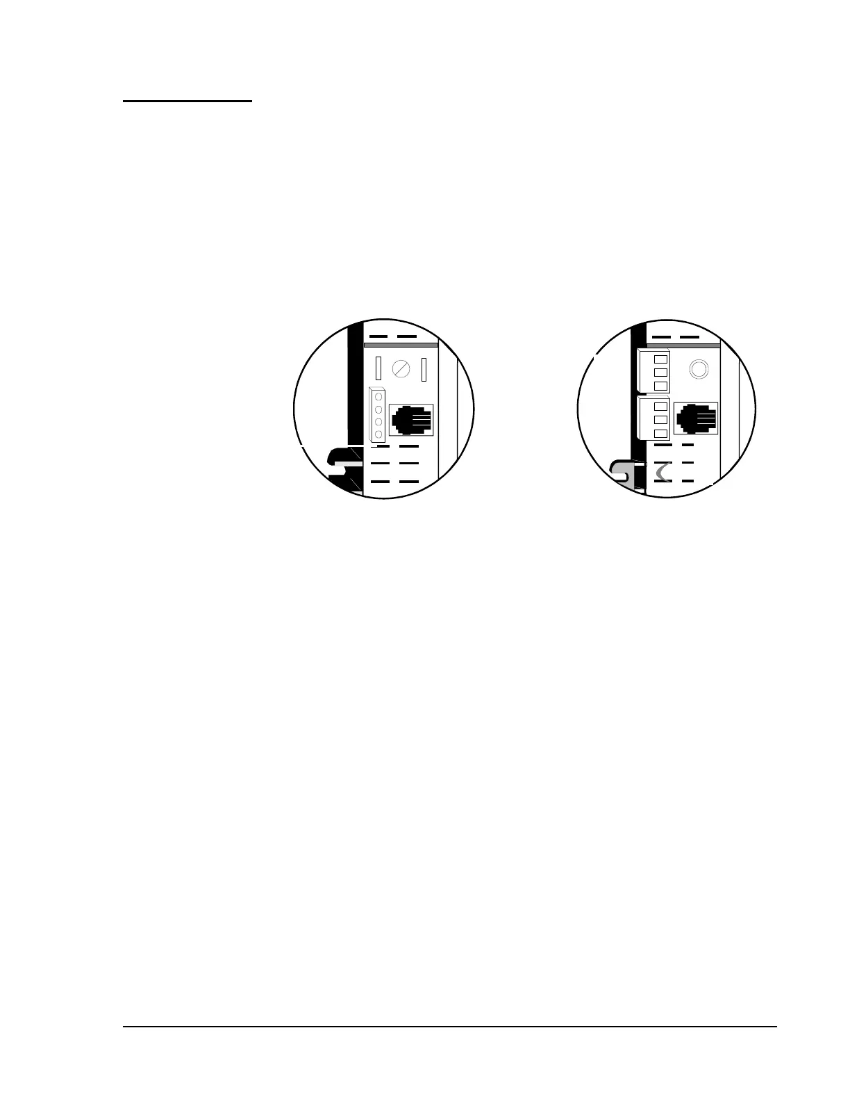
Note: The N2 terminal connectors on the new UNTxxx-1 series
controllers are different from the UNTxxx-0 series. The REF,
N2-, and N2+ terminations are arranged in different order (see
Figure 6).
24VAC
COM
ZBUS
REF
N2-
N2+
Triac
BO1
BO2
BO3
24 V
ZBUS
AREF
N2-
N2+
UNTxxx-0
UNTxxx-1
compare
Figure 6: N2 Terminal Connector Comparison
Terminal
Designations