UNT Controller—Unitary (UNT) Controller
35
You can obtain a Double-Pole, Double-Throw (DPDT) relay configuration
by connecting the BO signal to two terminals on the relay kit terminal
block (e.g., B and C). If you require a phone jack at a remote relay kit,
add an AS-CBLCON-0.
For additional information, refer to the grounding and isolation
information in the Wiring Details section of this technical bulletin.
Use 18 AWG twisted pair wire for all sensor and output wiring. Shielding
is not required. However, if you decide to use it, earth ground the shield at
the transformer. You may also use 24 AWG wire in some applications, but
maximum wire length will be reduced due to the increased resistance. To
minimize sensor error caused by field wiring, the total resistance of all
resistive sensor wiring should be less than 3.0 ohms.
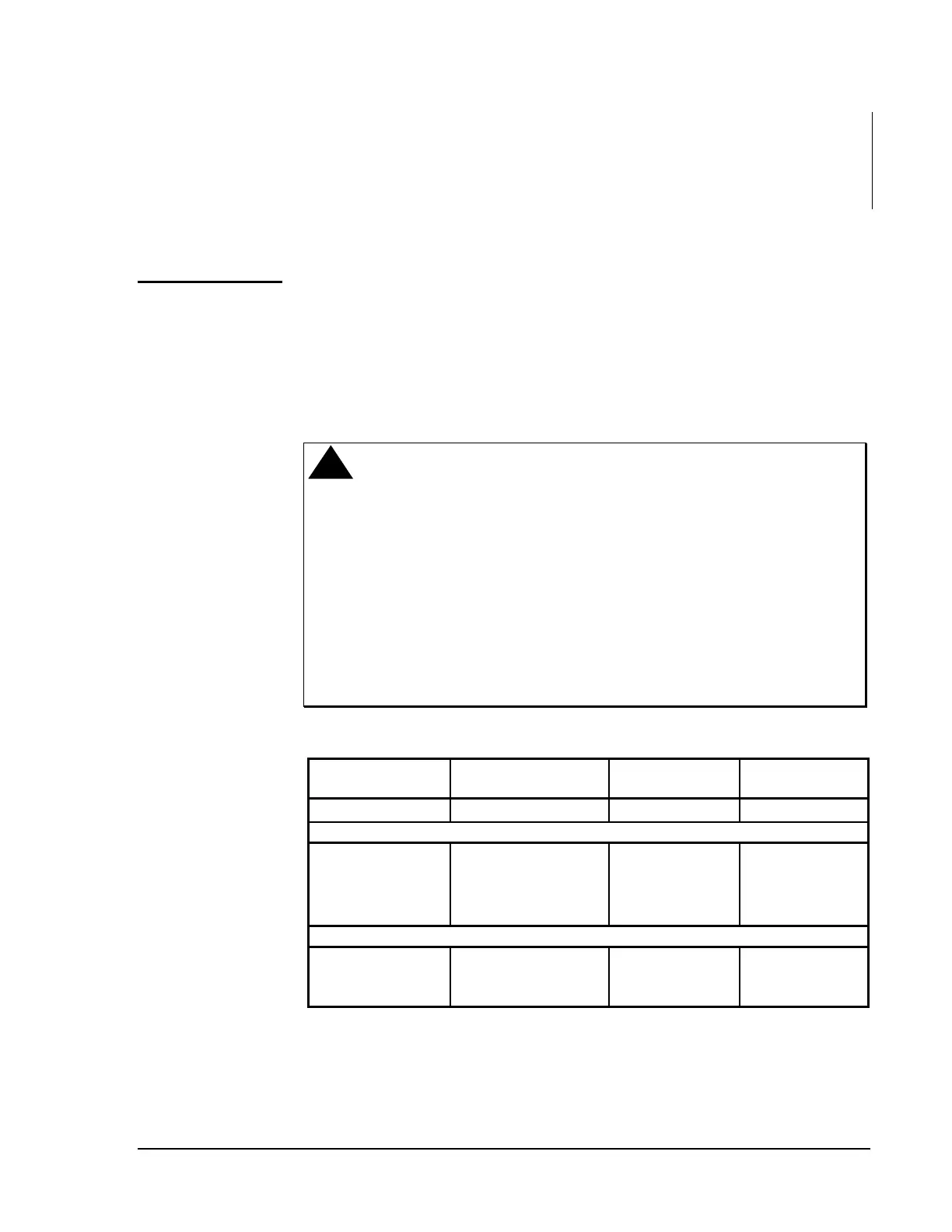
!
CAUTION: Do not run AI, BI, AO, BO, ZBUS, or N2 Bus
wiring in the same conduit as line voltage wiring
(30 VAC or above) or wiring that switches power to
highly inductive loads such as contactors, coils,
motors, or generators.
The insulator on the +15 VDC terminal prevents
inadvertent shorting to the adjacent 24 VAC
terminal. To prevent damage to the controller,
remove and discard this insulator only when you
need to use that specific terminal.
Table 11: Input and Output Load Impedances
Function Range
DC Input
Impedance
Sensor or Load
Impedance
DC Supply
14.6-17 VDC at 90 mA N/A 162-10M ohm
Inputs
AI Voltage
0-2V or 0-10 VDC 470k ohm 0-5k ohm
AI Temperature/
Potentiometer
1000 ohm Si, Ni, Pt, or
0-2k ohm Potentiometer
3540 ohm 0-2k ohm
BI VAC 60 Hz
0-24 VAC, 2.5V 470k ohm 0-5k ohm
Outputs
AO Voltage
0-10 VDC @ 10 mA
maximum
N/A 1k-10M ohm
BO VAC Triac
24 VAC @ 50-800 mA* N/A *30-480 ohm
* With total controller power draw limited as described previously.
Wiring Sensors
and Actuators