44
UNT Controller—Unitary (UNT) Controller
IMPORTANT: The N2+ and N2- lines must be twisted pair lines.
This allows most induced noise (common mode
noise) from external sources to affect both lines
equally, thereby canceling the noise.
Notes: Do not run N2 Bus wiring in the same conduits as line voltage
wiring (30 VAC or above) or wiring that switches power to highly
inductive loads (such as contactors, coils, motors, or generators).
For more N2 Bus overview information, refer to the ASC and N2
Bus Troubleshooting Technical Bulletin in FAN 636.3 or 1628.2.
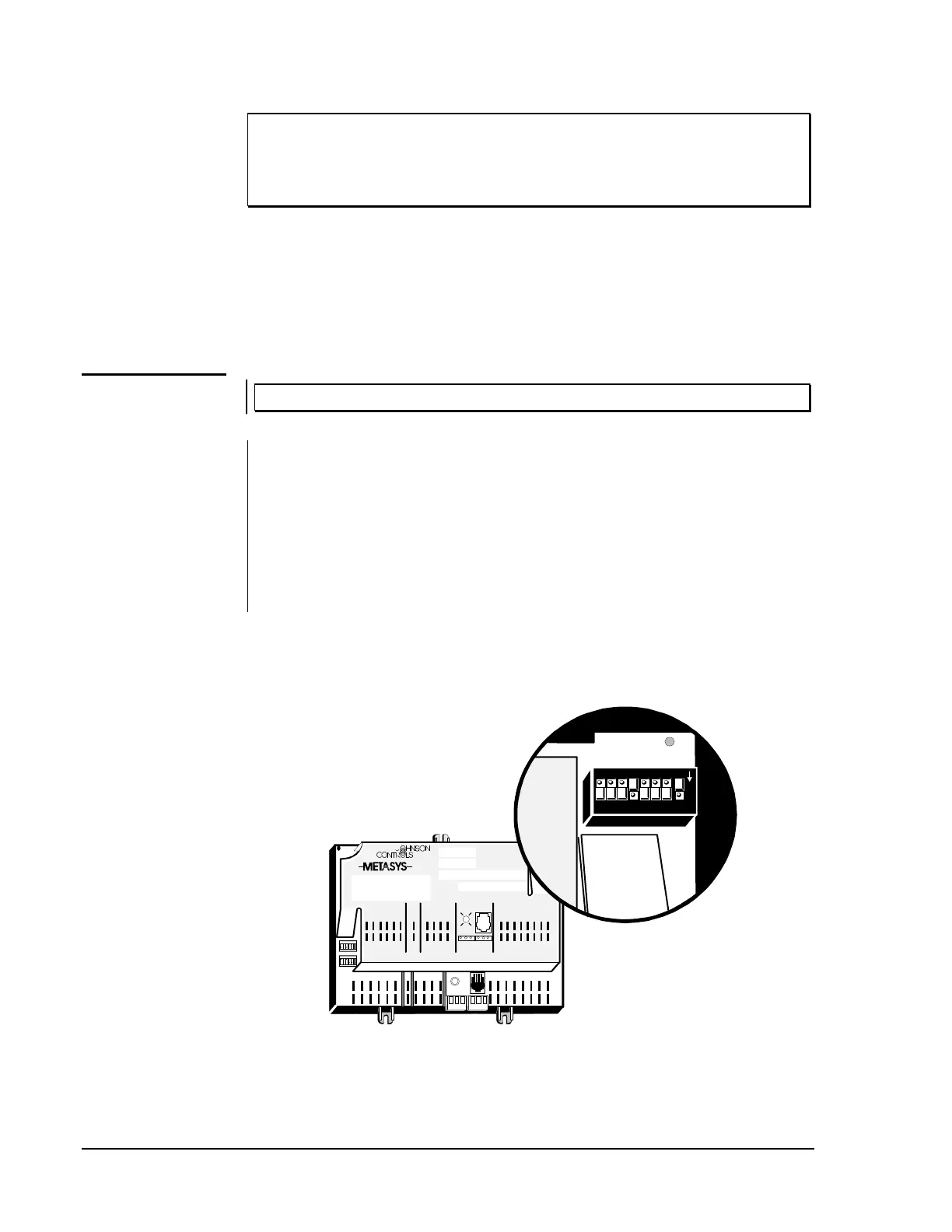
IMPORTANT: When setting the N2 Address, do not use Address 0.
Set the N2 address and test for N2 voltage, polarity, and isolation before
actually wiring the UNT for operation. The factory default address is 3.
The switches located in the upper right corner of the UNT must be set to
the same number as the software assigned to the module. The Metasys (or
Companion) Facility Management System (FMS) uses this address for
polling and commanding. The numbers are in binary format and
horizontally arranged, with the least significant digit on the right.
For example, if the controller address is 17 (decimal), the binary
representation is 00010001. Switches “1” and “16” must be set to the “on”
position (1 + 16 = 17), as shown in Figure 20.
1 2 3 4 5 6
1 2 3 4 5 6 7 8
BI NARY I NANALOG INPUTS BINARY OUTPUTS
TM
BI NARY I NPUTANALOG INPUTS
1 2 3 4 5 6 1 2 3 4
ANALOG INPUTS
COMMON
+1 5V D C
TO
ZONE
STAT
BINARY OUTPUT
2 4 VAC
1 2 3 4 5 6
+15VDC
24 VAC
COMMO N
COMMON
REF
N2-
N2+
24VAC
COM
ZBUS
Z BUS
DSI
7 8
TRACS
24 VAC
1 2 3 4 5 6
COMMON
CO MMON
COMMON
d-swtch
Address Switches
If you change the address while
the UNT is online, you must
cycle power for the network to
recognize the new address.
128
64
32
16
8
4
2
1
1
N
O
2 34567 8
Figure 20: Setting the N2 Address DIP Switches
Installing the
N2 Bus
Setting the
N2 Address