46
UNT Controller—Unitary (UNT) Controller
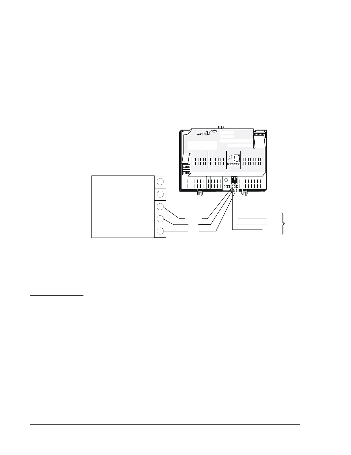
A hardware connection between the N2 Communications Bus and the
Companion PC/Panel/LTD is required to communicate with N2 devices.
An MM-CVT101-0 Communications Converter is required to network to
the PC Companion. See Figure 22 for terminal locations. Refer to the
Metasys Companion Technical Manual (FAN 628.1) for information
specific to the MM-CVT101 and the Companion Panel/LTD. Refer to the
Facilitator FMS Technical Manual (FAN 1628.1) for information specific
to the MM-CVT101 and the Facilitator Panel/LTD.
1 2 3 4 5 6 7 8
1 2 3 4 5 6
BINARY INANAL OG INPUTS BINARY OUTPUTS
BINARY INPUTAN ALOG IN PUTS
1 2 3 4 5 6 1 2 3 4
ANAL OG INPUTS
COMMON
TO
ZONE
STAT
BINARY OUTPUT
24VAC
1 2 3 4 5 6 7 8
24VAC
REF
N2-
N2+
24VAC
COM
ZBUS
Z BUS
DSI
1 2 3 4 5 6
24VAC
24VAC
24VAC
24VAC
24VAC
24VAC
BINARY COM
n2wire-b
RS232-to-N2 Bus
Converter
(N2 Bus Terminal)
REF
N2 -
N2 +
To
Next
N2
Device
N2 -
N2 +
Com
anion/Facilitator PC Version
N2 +
N2 -
N2 REF
9 VDC
9 V COM
MM-CVT101-0
N2 REF
Figure 22: Connecting the UNT Controller to Companion
Note: For more information on installing the N2 Bus, refer to the
ASC and N2 Bus Troubleshooting Technical Bulletin in FAN 636.3
or 1628.2.
The Zone Bus is a 2-wire communications bus that allows a computer to
communicate with the UNT, to download the UNT’s database, and to
communicate with the Zone Terminals and M100 actuators. A third wire
is used for 24 VAC power to the CBLPRO, Zone Terminal, and
AS-CBLCON. The bus interface sustains no damage in the presence of
fault voltages of 24 VAC or less.
M100 actuators should be powered with separate transformers; therefore,
only the Zone Bus and common wires need to be pulled.
See Table 15 for Zone Bus specifications.
N2 Wiring to
Companion
Zone Bus
Communications
Zone Bus
Description