UNT Controller—Unitary (UNT) Controller
33
Connect power to the relay module and the transformer through the
conduit knockouts in each box. Wire the module according to the
following diagrams. For a schematic diagram of the relay module, see the
AHU Tower Wiring Details section of the Air Handling Unit (AHU)
Controller Technical Bulletin in FAN 636.3 or 1628.2.
!
WARNING: Possible equipment damage or electrical shock.
Disconnect power circuit before wiring relay kit.
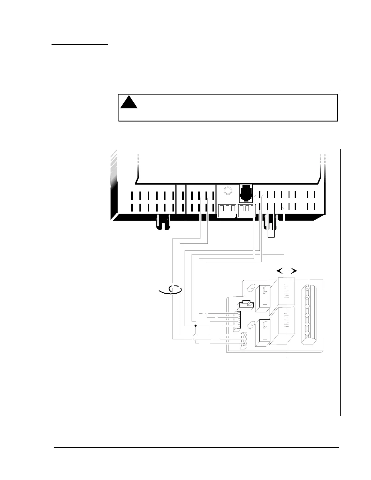
Figure 12 shows a UNT110/111 wired to an RLY050/002 with no BOs
isolated from earth ground.
BINARY IN
ANALOG INPUTS
BINARY OUTPUTS
AI CM
AI 1
AI CM
AI 2
AI CM
AI 3
AI CM
AI 4
AI CM
AI 5
AI CM
AI 6
+15VDC
24 VAC
BI 1
BI 2
BI 3
BI 4
+15VDC
BO 1
24VAC
BO 2
BO 3
BO 4
BO 5
BO 6
COMMON
TRIAC
BO 7
COMMON
COMMON
COMMON
COMMON
BO 8
24 VAC
24 VAC
24 VAC
24VAC
A
B
COM
NC
NO
COM
NC
NO
unt1ahu
AS-RLY050-0 / AS-RLY002-0
A
B
COILS
TRIAC
HAND
OFF
HOA
COM
Note 3
Jumper
Low
Voltage
High
Voltage
(See
Note 1.)
Note 1: Separate low voltage wiring on the left from line voltage wiring on the right.
Note 2: Hand operation using the H/O/A switch requires common to the COILS
terminal and 24 VAC to the TRIAC terminal to energize the relay.
Note 3: The Hand or Off position signals the binary input connected to those terminals.
These switches can be hardwire "OR"ed and connected to one BI. This
switch uses the HOA COM terminal, which is isolated from the relays.
Note 4: Your application will determine exact connections to UNT.
Figure 12: UNT110/111 Wired to RLY050/002
Wiring to
RLY050/002
Relays