UNT Controller—Unitary (UNT) Controller
39
1 2 3 4 5 6
1 2 3 4 5 6 7 8
BINARY I NANALOG INPUTS BI NARY OUTPUT S
TM
BINARY I NPUT
ANALOG I NPUTS
1 2 3 4 5 6
1 2 3 4
ANALOG I NPUTS
COMMON
+15VDC
TO
ZONE
STAT
BINARY OUTPUT
24VAC
1 2 3 4 5 6
+15VDC
24VAC
COMMON
COMMON
REF
N2-
N2+
24VAC
COM
ZBUS
Z BUS
DSI
7 8
TRACS
24 VAC
1 2 3 4 5 6
COMMON
COMMON
COMMON
Laptop PC
Laptop PC
CBLPRO
Metast at
or
6-pin to 6-pin
Zone Bus
9-pin or 25-pin
Adapter
9-pin or 25-pin
Adapter
8-pin
to
8-pin
untconn
6-pin to 8-pin
Zone Bus
or
6-pin
CBLPRO
Zone
Terminal
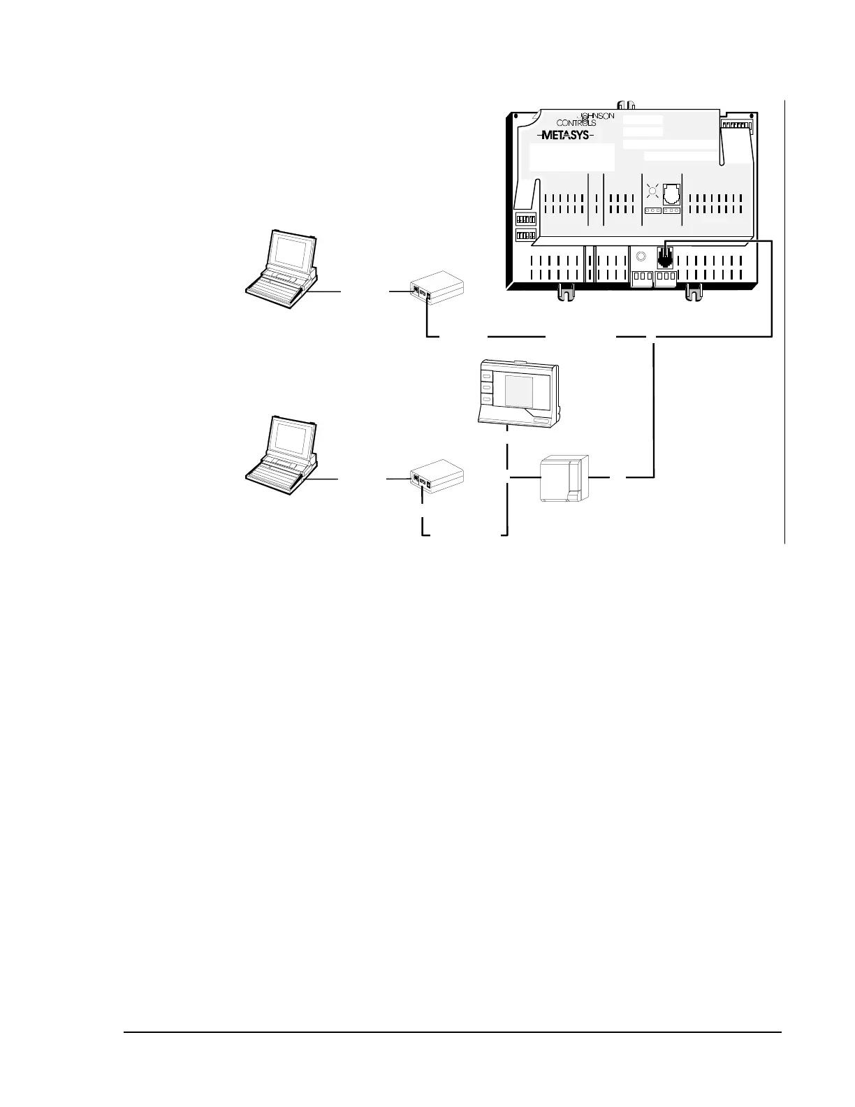
Figure 17: Example of Temperature Sensor Connection
To make all necessary wiring terminations between the UNT and
TE-6400/6500 series zone sensor, use phone cable that has preterminated
8-pin RJ-45 connectors. For cable ordering information, refer to Vendor
Code Numbers in the Ordering Information section of this technical
bulletin.
Connect one end of the cable to the Zone Bus connector on the controller
and the other end to the 8-pin connector on the back of the sensor as
shown in Figure 17.
In addition to the 8-pin RJ-45 connection, the TE-6410 sensor also has a
6-pin, RJ-12 connection under its cover. This allows remote connection of
the CBLPRO or the Zone Terminal (used for system monitoring.)
For UNT140/141 series controllers, there is an additional 6-pin jack for
Zone Bus communication. You may permanently connect a Metastat
to the 8-pin jack of the controller and simultaneously connect a
laptop PC/CBLPRO or Zone Terminal to the Zone Bus via the 6-pin jack.
Temperature
Sensors