80
UNT Controller—Unitary (UNT) Controller
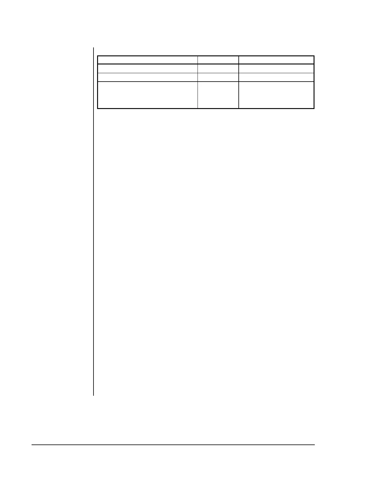
Table 38: Recommended Transformers
Transformer Type Power Description
Johnson Controls Y65 Series
40 VA 120 VAC to 24 VAC
Johnson Controls Y65G13-0
40 VA 24 VAC to 24 VAC
Johnson Controls AS-XFR050-0
50 VA 120 VAC to 24 VAC
(insulated split-bobbin
windings, high noise
immunity, resettable breaker)
3. Drive rooftop unit loads via pilot relays (see Figure 40) if any of
the following conditions exists:
•
The rooftop unit contains any contactor/relay coils that might be
energized by some means other than directly by the UNT’s
binary outputs. A common example of this is a time delay relay
contact closure in a BO circuit.
•
An individual BO load exceeds 800 mA.
•
All loads together will cause the UNT to require more than
40 VA of 24 VAC power when mounted in an enclosure, or more
than 75 VA when mounted in a well-vented open area.
•
Voltages other than 24 VAC need to be switched.
Note: Install pilot relays for isolation between the UNT and the
rooftop unit contactors/relays.
4. You may drive rooftop unit contactor/relay loads directly
(see Figure 39) if all of the following conditions exist:
•
Under normal operation, the UNT binary outputs directly drive
all contactor/relay coils within the rooftop unit.
•
Individual BO loads exceed 50 mA. (Required to keep the
triac on.)
•
Individual BO loads do not exceed 800 mA.
•
The UNT and all its loads together draw less than 40 VA of
24 VAC power when mounted in an enclosure, or less than
75 VA when mounted in a well-vented open area.
•
Triac load voltage is 24 VAC
±
5%.
Note: Connect the UNT binary outputs (triacs) to the rooftop unit
terminal strip.