114
JOHNSON CONTROLS
FORM 145.05-NOM1 708)
Coil Pressure Drop (FlexSys Units Only)
On FlexSys units a transducer is used to monitor the
pressure drop across the evaporator coil. This pressure
drop is used to verify supply fan operation and also used
to control the by pass damper to prevent excessive by
pass air resulting in the frosting of the evaporator coil.
The transducer is factory wired and tubing attached and
located on either side of the evaporator coil.
When verifying transducer operation, the technician
must insert a tee in each of the tubes connected to the
transducer to verify the differential pressure being
applied to the transducer. Once this pressure is known, a
comparison can be made of the duct pressure vs. output
milliamp values from the transducer. To check the
milliamp output from the transducer remove the wire
from the output (OUT) connection on the transducer and
connect your meter between the end of the wire and the
(OUT) terminal of the transducer. Table 24 shows the
relationship between the pressure applied to the duct
static pressure transducer and the output voltage. The
output is linear.
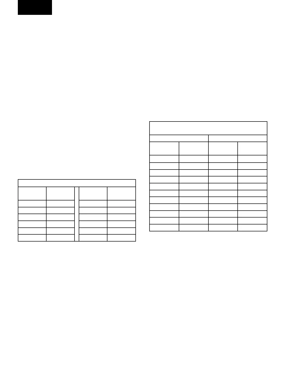
TABLE 24 – COIL PRESSURE DROP (FLEXSYS)
DIFF PRESS
(IN WC)
MA
OUTPUT
DIFF PRESS
(IN WC)
MA
OUTPUT
0.0 4.0 1.5 13.6
0.25 5.6 1.75 15.2
0.50 7.2 2.0 16.8
0.75 8.8 2.25 18.4
1.0 10.4 2.5 20.0
1.25 12.0
Discharge Pressure Transducer
A discharge pressure transducer is located on each of the
discharge lines leaving the compressors. The purpose
of the transducer is to sense and convert the discharge
pressure into a DC voltage. The DC voltage is then
sent to the Unit Control where it is used to control the
condenser water valve. The discharge pressure value,
in psig, is displayed by the User Interface.
The discharge transducer has a range of 0 to 400 psig,
with a linear output of 0 to 5 DC volts. Table 25
illustrates the DC volt output from the transducer for a
given discharge pressure.
Suction Pressure Transducer
A suction pressure transducer is located on each of the
suction lines entering the compressor. The purpose
of the transducer is to sense and convert the suction
pressure into a DC voltage. The DC voltage is then
sent to the Unit Control where it is used to verify proper
low side pressure. The suction pressure value, in psig,
is displayed by the User Interface.
The suction pressure transducer has a range of 0 to 150
psig, with a linear output of 0 to 5 volts DC. Table 25
illustrates the DC voltage output from the transducer
for a given suction pressure.
TABLE 25 – REFRIGERANT PRESSURE
TRANSDUCERS
SUCTION TRANSDUCER DISCHARGE TRANSDUCER
PRESSURE
PSIG
VOLTAGE
VDC
PRESSURE
PSIG
VOLTAGE
VDC
0 0.50 0 0.50
15 0.90 50 1.0
30 1.3 100 1.5
45 1.7 150 2.0
60 2.1 200 2.5
75 2.5 250 3.0
90 2.9 300 3.5
105 3.3 350 4.0
120 3.70 400 4.5
135 4.1
150 4.5
Humidity Sensor (FlexSys Units Only)
The humidity sensor outputs a 4 to 20 milliamp output
in response the relative humidity level of the supply
air. This value is used to determine the dew point of
the supply air entering the under floor space. The Unit
Control adjusts the supply air dew point to keep the
dew point temperature below the slab temperature of
the under floor area.
Service
 Loading...