107
JOHNSON CONTROLS
FORM 145.05-NOM1 (708)
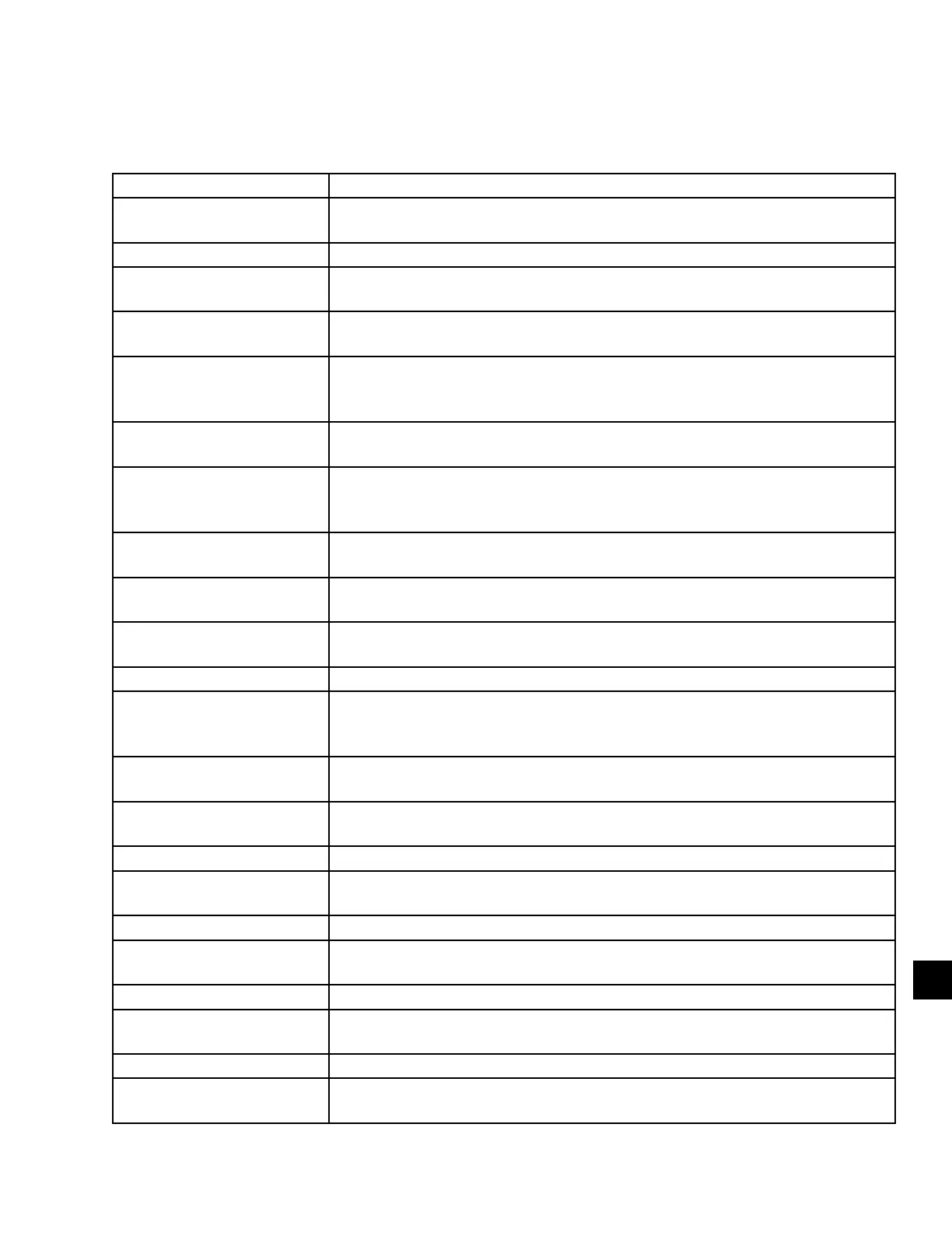
MENU ITEM DEFINITION
#OF SP SENSORS” This item is used to program the number of duct static inputs to the Unit Con-
troller. This can be set to 1 or 2
# OF COMP This is the number of compressors programmed in the software in the control.
# OF STAGES This is the number of stages of compressor operation programmed in the soft-
ware in the control.
AC – S/A DEW EN This enables dew point supply air temperature cooling control (FlexSys units
only).
AC DX TEMP This is the coil temperature cooling PID loop generated by comparing the DX
coil temperature to 40.0° F. This is a reverse acting PID loop, as the temperature
approaches 40.0° F the output increases. (FlexSys units only).
AC R/A TEMP This is the return air cooling PID loop generated by comparing the return air
temperature to the AC/Econ-R/A SP.
AC S/A DEW This is the DEW POINT COOLING PID loop generated by comparing the dew
point temperature of the supply air to a derived dew point temperature set point
(FlexSys units only).
AC S/A TEMP This is the supply air cooling PID loop generated by comparing the supply air
temperature to the AC/Econ-S/A SP.
AC/ECON-RA SP This item is used to program the return air temperature set point for cooling or
economizer operation.
AC/ECON-S/A SP This item is used to program the supply air temperature set point for cooling or
economizer operation.
AC-R/A TEMP EN This item is used to enable and disable cooling Return Air Temperature Control.
AC-S/A DEW DIF This item is used to program the offset from the Slab Temperature that the con-
trol will use in deriving the DEW POINT COOLING PID loop (FlexSys units
only).
AC-S/A DEW MAX This item is used to program the maximum value for the derived cooling dew
point set point (FlexSys units only).
AC-S/A DEW MIN This item is used to program the minimum value for the derived cooling dew
point set point (FlexSys units only).
AC-S/A TEMP EN This item is used to enable and disable cooling Supply Air Temperature Control.
AIR FLOW SWITCH This gives the status of the air proving switch in the unit. It should show ON
when the blower is operating and OFF when the blower is turned off.
ALARM OUT This is the status of the digital fault alarm output.
ALARM OUTPUT This Item is used to force the normally OPEN contacts that signify a fault to
CLOSE.
AUX DAMPER This is not used in this product.
AUX FAN OUT This item is used to force the normally OPEN contacts that signifies the supply
fan is on to CLOSE.
B/P DAMPER MOD This is the analog output to the by-pass damper (FlexSys units only).
BOX OPEN This item is used to force the normally OPEN contacts used to open the VAV
boxes to CLOSE.
7
Continued on next page
SECTION 7 – PARAMETER DESCRIPTIONS AND OPTIONS
TABLE 20 – DEFINITIONS
 Loading...