119
JOHNSON CONTROLS
FORM 145.05-NOM1 (708)
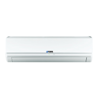
Auxiliary Control Board
The Analog Inputs (IN-1-IN-8) on the auxiliary control
board can be configured for the following type of
inputs:
• Thermistor – temperature input
• Dry contact – on / off binary input
• 0 – 5 VDC
Tables 27-30 identify the type of input device connected
to each of the analog inputs for the various Versecon
configurations. The configuration of the input
connection must match the type of input identified in
the table.
The pin positions for each configuration are shown in
Fig. 8.
THERMISTOR /
DRY-CONTACT
0 - 5 VDC
FIG. 8 – AUXILIARY CONTROL BOARD PIN
POSITIONS
LD12428
8
FIG. 10 – AUXILIARY CONTROL BOARD
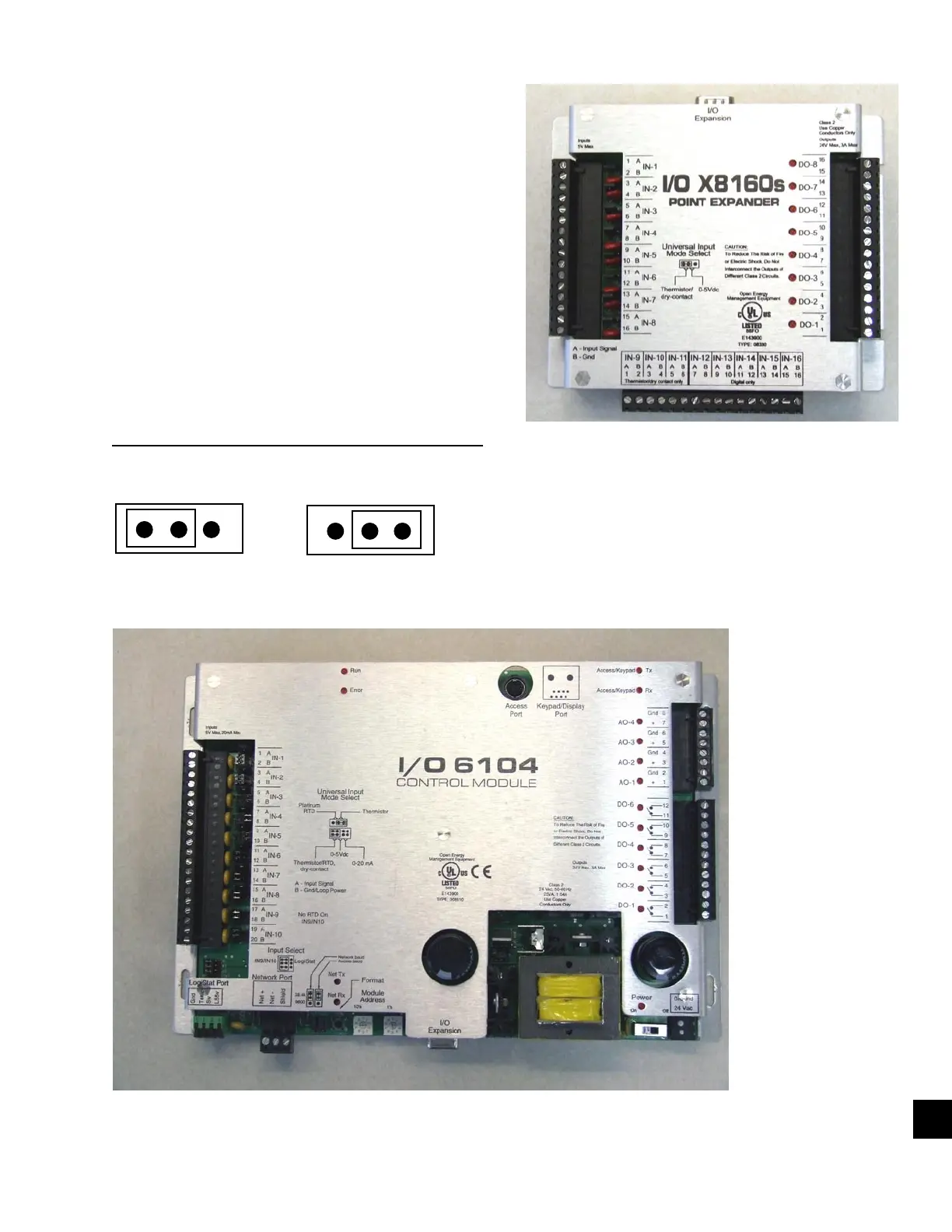
FIG. 9 – MAIN CONTROL BOARD
 Loading...