28
JOHNSON CONTROLS
FORM 145.05-NOM1 (708)
For unit in the cooling mode:
MOP = 2.25 (largest motor RLA or FLA) + other
loads + 2 amps.
For units in the heating mode:
With Electric Heater KW 50 KW or less:
MOP = 2.25(electric heat FLA + supply fan
motor amps) + 2 amps.
With Electric Heater KW greater than 50KW:
MOP = 2.25 (supply fan motor amps) + elec-
tric heat FLA + 2 amps.
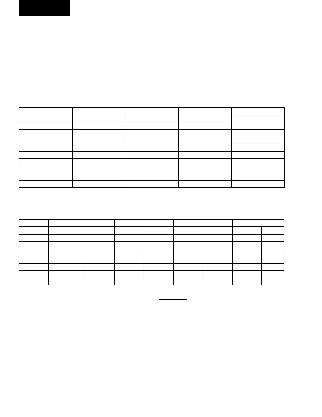
HORSEPOWER 208/60/3 FLA 230/60/3 FLA 460/60/3 FLA 575/60/3 FLA
3 8.8 8.6 4.3 3.8
5 14.2 13.2 6.6 5.9
7.5 21.4 19.6 9.8 8.4
10 28.6 26.4 13.2 10.4
15 42.0 39 19.5 16.0
20 55.0 50.0 25.0 20.0
25 66.0 60.0 30.0 26.0
30 80.0 70.0 35.0 28.5
40 110.0 93.0 46.0 36.1
50 137.0 118.0 59.0 46.5
TABLE 8 – FAN MOTOR DATA
TABLE 9 – COMPRESSOR MOTOR DATA
HP 208/60/3 230/60/3 460/60/3 575/60/3
RLA LRA RLA LRA RLA LRA RLA LRA
4 12.1 91.0 10.9 91.0 5.5 50.0 4.4 37.0
7 19.6 164.0 17.7 164.0 9.7 100.0 7.8 80.0
10 31.2 239.0 28.2 239.0 14.1 125.0 11.3 80.0
12 34.4 245.0 31.1 245.0 15.5 113.0 12.5 100.0
15 42.1 425.0 38.0 425.0 19.0 187.0 15.2 148.0
20 57.5 500.0 52.0 500.0 26.0 250.0 20.8 200.0
25 74.4 500.0 67.2 500.0 32.0 250.0 25.6 200.0
Contact the factory for electric heat full load amp
data.
Field Control Wiring
The unit has three sets of 24-volt AC/DC dry contacts
rated at 3 amps maximum that are normally open. The
following is a description of each of the contacts.
Pump Start
Contact DO-6 on the Unit Control Board closes
whenever the Unit Control is in the on mode, either by
the ON switch, the internal schedule, or a communicated
ON input. This contact can be used to energize the
condenser water pump. The connection point for this
feature is terminals 9 and 10 of the low voltage terminal
block.
Installation
 Loading...