2-6
● Installation Procedure
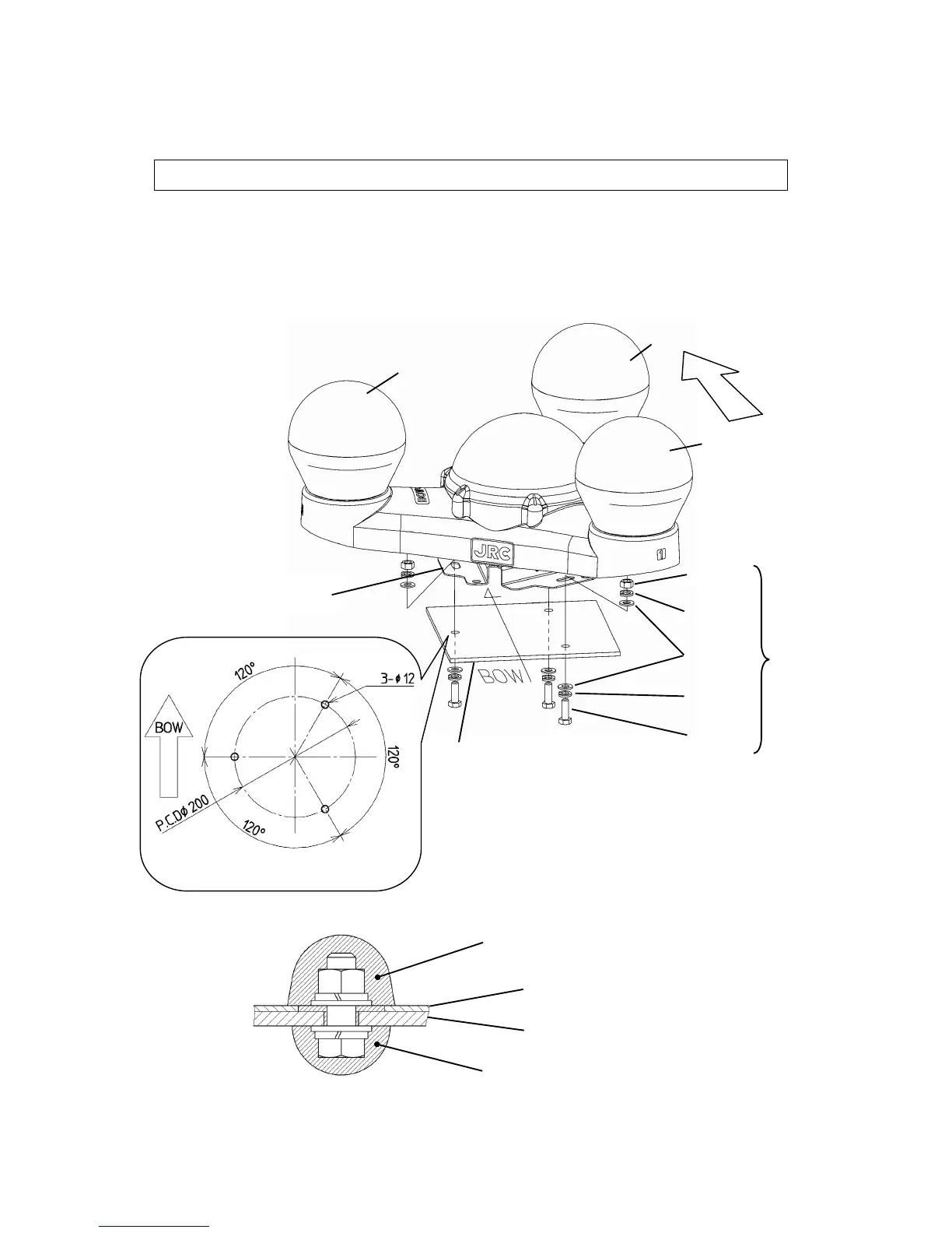
The unit shown in the figure is the NNN-20, which is almost identical to the NNN-30.
1. Provide a mounting plate as shown below, and secure the sensor unit. Use M10 hex bolts,
washers, spring washers, and nuts to secure it. Tighten the bolt by 3430 N-cm of torque
(350 kg-cm).
When making holes in the mounting plate, beware of bow direction. Excessively long bolts
may reach the sensor unit. For 5 mm (1/5 inch) mounting plate, M10 x 30 mm bolts are just
fit. Using double nuts is also effective to fix plate permanently.
2. Use RTV rubber to cover the hex bolts and nuts.
Mount
Sensor Mounting Plate
Apply RTV rubber
Apply RTV rubber
Mount
(Dockyard Supply)
GPS3
GPS1
GPS2
Hex Bolt
(SUS)
Flat
Washer
(SUS)
Spring
Washer