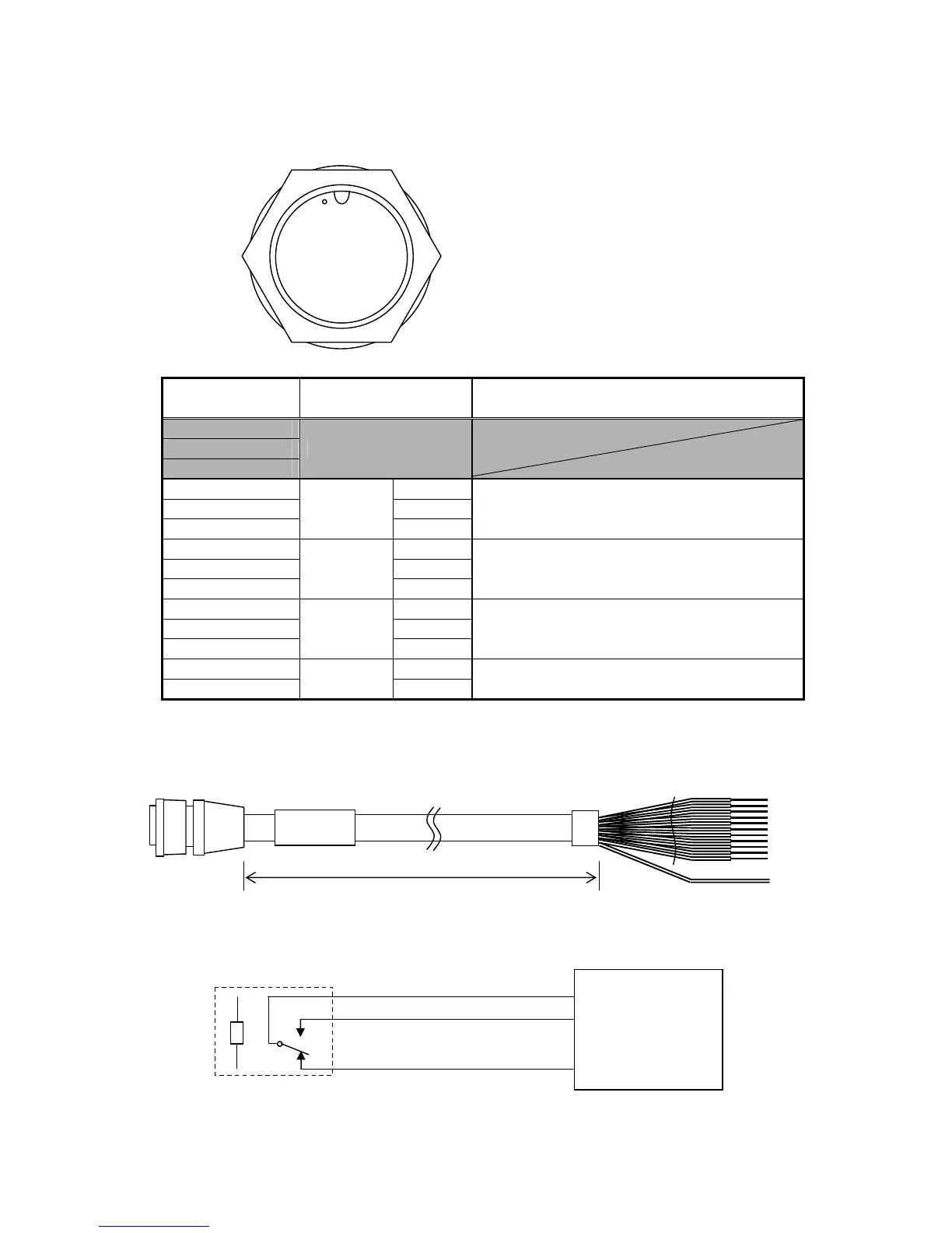
2-20
[Contact Signal IN/OUT Connector]
CONTACT IN/OUT
Data Cable: CFQ-5404 (option)
Terminal Number
(CFQ-5404)
Name Explanation
1
2
3
Unused
4 (Yellow) COM
5 (Green) NO
6 (Blue)
Contact
Output 0
NC
Outputs external buzzer 1.
(Outputs when alarm is generated)
7 (Purple) COM
8 (Grey) NO
9 (White)
Contact
Output 1
NC
Outputs contact signal (log pulse).
(Refer to "5.3.7 Data I/O Settings (DATA I/O)")
10 (Black) COM
11 (Pink) NO
12 (Light Blue)
Contact
Output 2
NC
Outputs external buzzer 2.
(Outputs when alarm is generated)
13 (Light Green) ACKIN+
14 (Light Brown)
Contact
Input
ACKIN-
Clears [Contact Output 2].
(by short-circuiting both terminals)
NO: Normally Open NC: Normally Closed
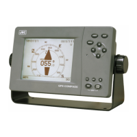
Appearance of Connection Cable
① ②
③ ④ ⑤
⑥ ⑦ ⑧ ⑨
⑩ ⑪ ⑫
⑬ ⑭
CFQ-5404
3m
COM
NO
NC
Relay
Maximum Contact DC30V / 1.0A
External Device