8.3 Performance Check
yyyy
yyyy
[IV] Performance Monitor (MON Display)
Note: The radar system is equipped with an interswitch.
For checking the performance unit, set the interswitch connection to straight, i.e. No.1 scanner is
connected to No.1 display unit as the Master.
[I] Check the Transmitter System (Transmitter System)
Procedures 1. Check the attenuation value.
* Transmitter System
(Initial value : 8.0)
Attenuation Value
Normal operating range : -6.9dB to +2.0dB
Performance degradation range : -15.0dB to -7.0dB
Note: About one minute after opening this menu item, check the transmitter attenuation value.
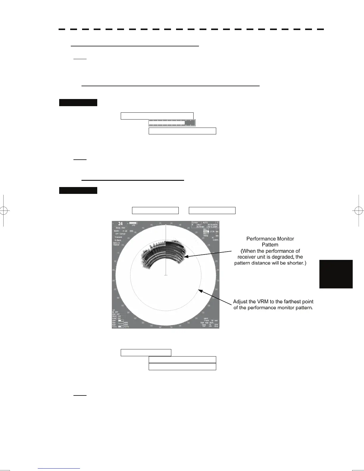
[II] Check the Receiver System
Procedures 1. Turn the [VRM] dial to make adjustments so that the farthest point of
the performance monitor pattern.
The Attenuation Value of *Receiver System is displayed.
8
2. Check the attenuation value.
* Receiver System
MON Pattern Range (Initial value : 18.0NM)
Attenuation Value
Normal operating range : -2.9dB to +3.5dB
Performance degradation range : -15.0dB to -3.0dB
Note: If Receiver System Attenuation Value display is under -3 dB or Transmitter System Attenuation
Value display is under -7 dB with the performance monitor test, radar should be checked by service
engineer. This means that the TX/RX unit may be faulty. Consult with the near-by dealer or our
sales department.
8-10

 Loading...