JMA-9100/7100 Installation Manual > 2.INSTALLATION OF SCANNER UNIT > 2.1 EQUIPMENT CABLE
2-3
2
2.1.3 2695111153
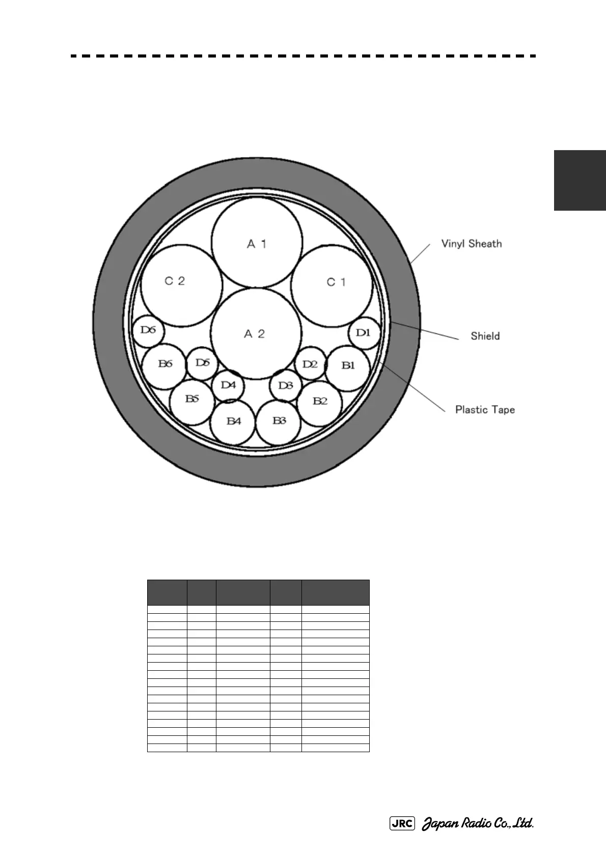
This is an 18-core shielded composite cable.
This cable is used to connect an interswitch to the display unit.
Fig 2-3: Cross-sectional drawing of 2695111153
maximum diameter 18.0mm
Table2-3: 2695111153 wire
Wire NO. Cross
Section
(m2)
No. of wire / φ Color
Remarks
A1 0.5 19 / 0.18 Black 1 Coaxial
A2 0.5 19 / 0.18 Black 2 Coaxial
B1 0.5 19 / 0.18 Blue Shield
B2 0.5 19 / 0.18 Yellow Shield
B3 0.5 19 / 0.18 Green Shield
B4 0.5 19 / 0.18 Red Shield
B5 0.5 19 / 0.18 Purple Shield
B6 0.5 19 / 0.18 Clear Shield
C1 0.3 12 / 0.18 Blue 2 Cores Shield
0.3 White
C2 0.3 12 / 0.18 Yellow 2 Cores Shield
0.3 White
D1 0.5 19 / 0.18 Brown
D2 0.5 19 / 0.18 Black
D3 0.5 19 / 0.18 Orange
D4 0.5 19 / 0.18 Gray
D5 0.5 19 / 0.18 Pink
D6 0.5 19 / 0.18 SkyBlue

 Loading...


