2-2
JMA-9100/7100 Installation Manual > 2.INSTALLATION OF SCANNER UNIT > 2.1 EQUIPMENT CABLE
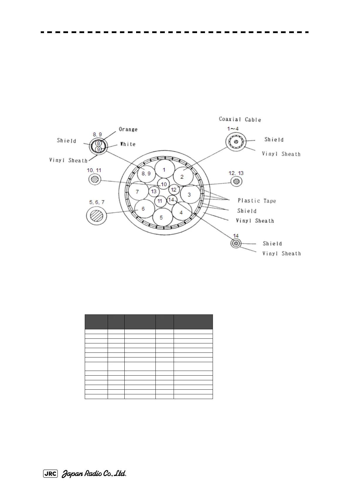
2.1.2 2695110056
This is a 14-core shielded composite cable.
This cable is used to connect an NKE-1125 type scanner or an NKE-1130 type
scanner, and an NTG-3225 type transmitter-receiver or a NTG-3230 type
transmitter-receiver to the display unit.
Fig 2-2: Cross-sectional drawing of 2695110056
maximum diameter 23.0mm
Table2-2: 2695110056 wire
Core (No.) Cross
Section
(m2)
No. of wire / φ Color
Remarks
1 0.5 19 / 0.18 Black 1 Coaxial Cable
2 0.5 19 / 0.18 Black 2 Coaxial Cable
3 0.5 19 / 0.18 Black 3 Coaxial Cable
4 0.5 19 / 0.18 Black 4 Coaxial Cable
5 5.5 35 / 0.45 Yellow
6 5.5 35 / 0.45 Green
7 5.5 35 / 0.45 Brown
8 0.3 12 / 0.18 White Twisted pair cable with
Shield sheath white
9 0.3 12 / 0.18 Orange
10 2 37 / 0.26 Red
11 2 37 / 0.26 Blue
12 1.25 50 / 0.18 Black
13 1.25 50 / 0.18 Purple
14 0.5 1 / 0.18 Gray Shield wire
 Loading...


