– 3 –
1) Carry the sewing machine with two persons as
shown in the gure above.
(Caution) Do not hold the handwheel.
2) Do not put protruding articles such as the screw-
driver and the like at the location where the sew-
ing machine is placed.
3) The under cover should rest on the four cor-
ners of the mach
ine table groove. Mount rubber
hinge seat
8
on the table and x it on the table
w
ith a nail.
4) Fix two rubber seats
1
on side
A
(operator’s s
ide) using nails
2
as
illustrated above. Fix two cushion seats
3
on side
B
(h
inged side) using a rubber-based adhesive. Then place under cover
4
on the xed seats.
@
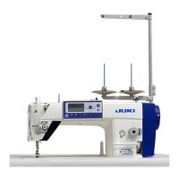
. SET-UP
1
1
3
3
8
1
2
4
3
A
B
1
2
4
3
A
B
Needle bar side
!0
7
8
7
6
9
!2
!1
5) Fit knee lifter pressing rod
6
. F
it hinge
7
into the opening in the machine bed, and t the machine head
to table rubber h
inge
8
before plac
ing the machine head on cushions
9
on the four corners.
6)
Securely attach head support rod
!0
to the table unt
il it goes no further.
(Caution) Be sure to install the machine head support bar supplied with the unit.
7) Draw out cable
!1
of the control box through cable draw-out hole
!2
to route
it to the underside of the
sewing machine table.
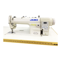
19.5mm
23mm
19.5mm
23.5mm
C
ontrol box side
1. Installation