17
8 Setting the limit contacts
Preparation ✱ Open the instrument ➩ "Opening the instrument", page 11.
✱ Connect supply voltage ➩ "Connection", page 12ff.
✱ Connect multimeter ➩ "Connection", page 12ff.
✱ Wait for instrument to warm up (approx. 1hour).
Defining the
switching range
(only for "+/-"
ranges)
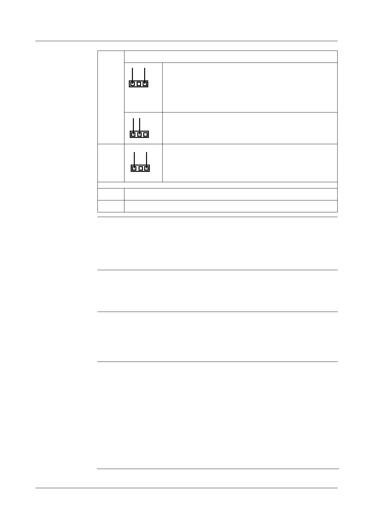
✱ Use jumper J1 (for GK1) or J2 (for GK2) to determine whether the limit
contact switches in the positive or the negative pressure range. For jumper
functions, see table above.
Setting the
relay function
✱ Use jumper J3 (for GK1) or J4 (for GK2) to determine whether the relay
switches as max. limit contact (relay switches when the actual value is
larger than the setpoint) or as min. limit contact (relay switches when the
actual value is smaller than the setpoint). For jumper functions, see table
above.
Setting the limit
contact with a
reference
pressure
measuring
device
✱ Set switch-on and switch-off delay to 0 (turn fully to the left) by using the
potentiometer TP3/7 or TP4/8.
✱ Apply the pressure at which the limit contact has to switch to the pressure
transmitter.
✱ Keep on adjusting the potentiometer TP1 (for GK1) or TP5 (for GK2), until
LED GK1 or GK2 lights up.
✱ Apply the pressure at which the limit contact has to switch back to the
pressure transmitter.
✱ Keep on adjusting the potentiometer TP2 (for GK1) or TP6 (for GK2), until
the LED GK1 or GK2 goes dark.
ST4 Multimeter connection for testing limit contact 2 (GK2)
1-3 => switching point of limit contact
Example 1: measuring range 0—3 hPa,
switching point at 1.5 hPA (50%) => 0.5 V
Example 2: measuring range -2 to +8 hPa,
switching point at +3.5 hPA (55%) => 0.55 V
1-2 => hysteresis of limit contact
Example: limit = 0.5 V,
hysteresis = 10% => 0.45 V
ST5 Multimeter connection for testing GK2
GK1 LED GK1
GK2 LED GK2
1
2
3
1
2
3
1
2
3