B 3
1003.GB
2.1 Truck
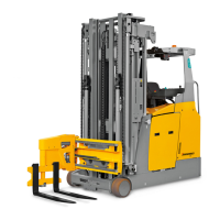
Safety Instructions: An enclosed vehicle design with rounded edges facilitates safe
handling of the ETM/V 214/216. The driver is protected by the driver’s cab (2). The
drive wheel (7) and the load wheels (5) are protected by a solid anti-crash
mechanism.
By activating the emergency switch all electrical power can be cut off in dangerous
situations. The driver’s display unit (12) shows the following conditions:
– Lift limit reached (o)
– Slow travel
– Service interval expired (service mode active)
– Overtemperature
– Battery latching unlocked
– Parking brake applied
– Forks horizontal (o)
– Sideshifter in central position (o)
– Dead man pedal (safety switch) not activated
– System warning / system fault
Line break safety devices in the lift cylinders limit the lowering speed of the load in the
event of a hydraulic system failure.
Display Instruments: Driver display (12) with large surface display using TFT
technology (t) or on board computer with LCD display (o), each with integrated
residual time display, battery charge status, lift and drive profile settings and steering
angle mode display.
Traction Drive: The complete drive unit is enclosed in the vehicle chassis. A 6.9 kW
fixed threephase motor operates the drive wheel (7) via a bevel spur gearbox.
The electronic traction current control system ensures the smooth rotation of the drive
motor and as a result smooth driving, powerful acceleration and electrically controlled
braking with energy recovery.
The degree of energy recovery can be adjusted via the driver’s display unit.
B 3
1003.GB
2.1 Truck
Safety Instructions: An enclosed vehicle design with rounded edges facilitates safe
handling of the ETM/V 214/216. The driver is protected by the driver’s cab (2). The
drive wheel (7) and the load wheels (5) are protected by a solid anti-crash
mechanism.
By activating the emergency switch all electrical power can be cut off in dangerous
situations. The driver’s display unit (12) shows the following conditions:
– Lift limit reached (o)
– Slow travel
– Service interval expired (service mode active)
– Overtemperature
– Battery latching unlocked
– Parking brake applied
– Forks horizontal (o)
– Sideshifter in central position (o)
– Dead man pedal (safety switch) not activated
– System warning / system fault
Line break safety devices in the lift cylinders limit the lowering speed of the load in the
event of a hydraulic system failure.
Display Instruments: Driver display (12) with large surface display using TFT
technology (t) or on board computer with LCD display (o), each with integrated
residual time display, battery charge status, lift and drive profile settings and steering
angle mode display.
Traction Drive: The complete drive unit is enclosed in the vehicle chassis. A 6.9 kW
fixed threephase motor operates the drive wheel (7) via a bevel spur gearbox.
The electronic traction current control system ensures the smooth rotation of the drive
motor and as a result smooth driving, powerful acceleration and electrically controlled
braking with energy recovery.
The degree of energy recovery can be adjusted via the driver’s display unit.
 Loading...