5. Install the replacement fan.
6. Tighten the captive screws on the faceplate of the fan module by using your fingers. If you are unable
to tighten the captive screws by using your fingers, use the screwdriver.
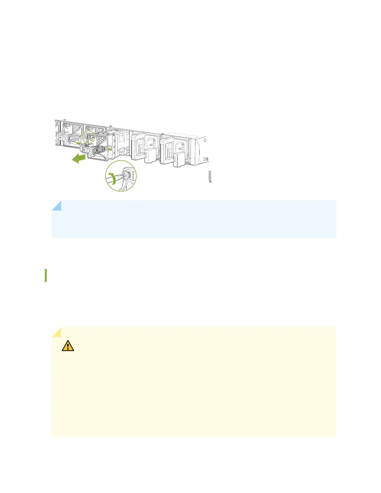
Figure 46: Removing a Fan Module from an EX4650 Switch
NOTE: Both the fan modules must be installed and operational for optimal functioning of the
switch.
Installing a Fan Module in an EX4650 Switch
EX4650 is shipped with redundant fans (4+1). Each fan module is a hot-removable and hot-insertable
field-replaceable unit (FRU) installed in the rear panel of the switch. You can remove and replace it without
powering off the switch or disrupting switch functions.
CAUTION: Do not mix:
•
Fan modules with different airflow labels (AIR IN (AFI) and AIR OUT (AFO)) in the same
chassis.
•
Power supplies with different airflow labels (AIR IN (AFI) and AIR OUT (AFO)) in the
same chassis.
•
Power supplies and fan modules with different airflow labels (AIR IN (AFI) and AIR
OUT (AFO)) in the same chassis.
•
AC and DC power supplies in the same chassis.
110