• For QFX5200-32C and QFX5200-32C-L, two 10-32 x 0.25 screws with #10 split-lock washers—Two
screws are used to secure the grounding lug to the grounding lug bracket protecve earthing
terminal. These screws and washers are not provided.
• For QFX5200-48Y, two 4.3 ring terminals, 14-18 AWG, and the provided M4 screw with star washer.
• Number 2 screwdriver.
An AC-powered QFX5200 switch chassis gains addional grounding when you plug the power supply in
the switch into a grounded AC power outlet by using an AC power cord appropriate for your
geographical locaon. See "QFX5200 Power Cord Specicaons" on page 43.
To connect earth ground to a QFX5200-32C or QFX5200-32C-L:
1. Connect one end of the grounding cable to a proper earth ground, such as the rack in which the
switch is mounted.
2. Place the grounding lug aached to the grounding cable over the protecve earthing terminal.
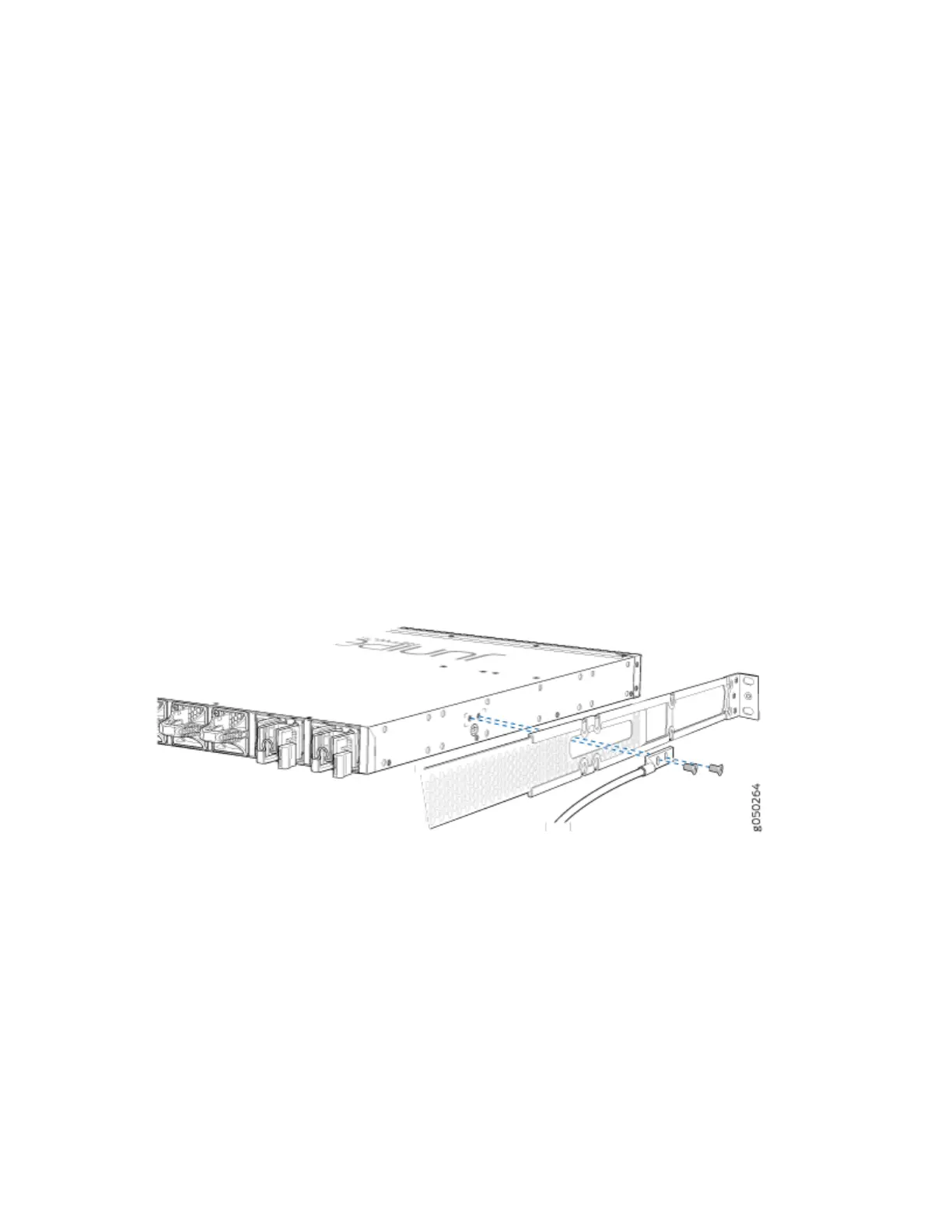
3. Secure the grounding lug to the protecve earthing terminal with two screws and washers. See
Figure 49 on page 110.
Figure 49: Connecng a Grounding Cable to a QFX5200-32C and QFX5200-32C-L
4. Dress the grounding cable and ensure that it does not touch or block access to other device
components and that it does not drape where people could trip over it.
To connect earth ground to a QFX5200-48Y:
1. Ensure the rack is properly grounded and is in compliance with ETSI ETS 300 253.
2. Verify that there is a good electrical connecon to the grounding point on the rack.
3. Aach the ring terminals to each end of the #14 AWG grounding wire.
4. Connect one of the ring terminals to the grounding point on the FRU panel.
110