Figure 9 on page 20 describes the connecons and components of the QFX5200-32C and
QFX5200-32C-L management panel.
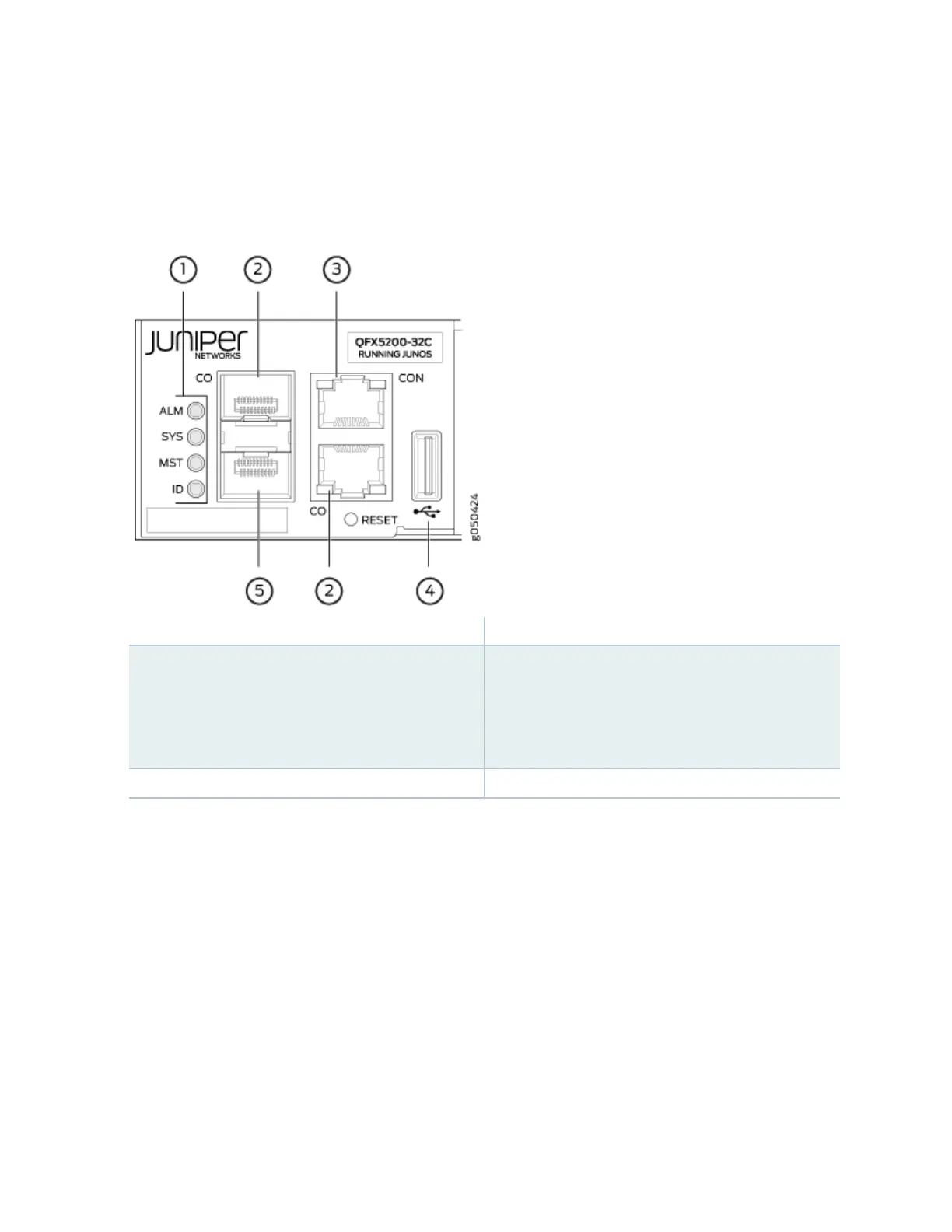
Figure 9: Management Panel Components on QFX5200-32C and QFX5200-32C-L
1—
Status LEDs
4—
USB port
2—
QFX5200-32C—Use C0 for the em0
interface using either RJ-45 (1000 Base-T) or
ber SFP connecons. QFX5200-32C-L –use
C0 for the re0:mgmt-0 management
interface.
5—
For QFX5200-32C only–em1–SFP
management Ethernet port (C1)
Cage (socket for either 1 GbE copper SFP or
ber SFP).QFX5200-32C-L does not support
a second management interface.
3—
RJ-45 console port (CON) )
The management panel consists of the following components:
• Chassis status LEDs
• Switch product number
• Management Ports C0 and C1
• C0–Use the RJ-45 connectors for 10/100/1000 BaseT or to cable a virtual management Ethernet
(VME) interface for spine members in a VCF. See "Connect a Device to a Network for Out-of-
Band Management" on page 106.
20