•
If you are mounting the device in a rack with other equipment, or if you are placing it
on the desktop near other equipment, ensure that the exhaust from other equipment
does not blow into the intake vents of the chassis.
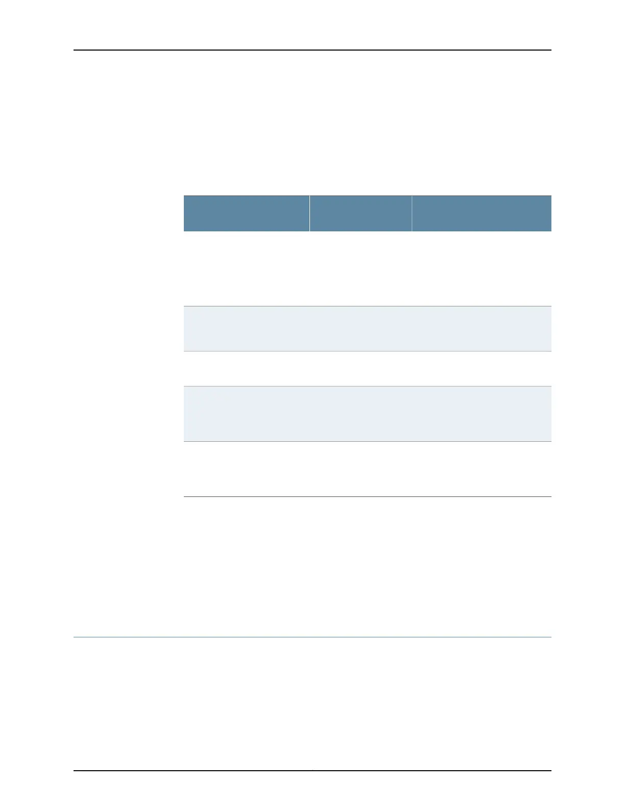
Table 16 on page 32 provides information on the clearance requirements for maintaining
the optimum airflow and the distances for facilitating easy maintenance of the device.
Table 16: Clearance Requirements for the Services Gateway
Requirement for Clearance
Recommended
ClearanceLocation
Space for service personnel to
remove and install hardware
components
NOTE: More space is required for
installing and removing Mini-PIMs.
2.5 in. (6.35 cm)Front of the chassis
Space for service personnel to
remove and install hardware
components
2.5 in. (6.35 cm)Rear of the chassis
Space for cable management and
organization
2.5 in. (6.35 cm)Between front-mounting flange
and rack or cabinet edge
Space for the cooling system to
function properly and to maintain
unrestricted airflow around the
chassis
2.5 in. (6.35 cm)Between side of the chassis and
any non-heat-producing
surface such as a wall or
cabinet side
Space for the cooling system to
function properly and to maintain
unrestricted airflow around the
chassis
2.5 in. (6.35 cm)Between side of the chassis and
devices that have fans or
blowers
Related
Documentation
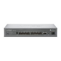
SRX220 Services Gateway Description on page 3•
• General Site Guidelines for Installing the SRX220 Services Gateway on page 29
• Site Preparation Checklist for the SRX220 Services Gateway on page 27
• SRX220 Services Gateway Cabinet Requirements on page 29
• SRX220 Services Gateway Rack Requirements on page 30
SRX220 Services Gateway Power Specifications and Requirements
The AC power system electrical specifications for the SRX220 Services Gateway are
listed in Table 17 on page 33.
Copyright © 2012, Juniper Networks, Inc.32
SRX220 Services Gateway Hardware