1. Ensure that the voltage across the DC power source cable leads is 0 V and that there is no chance that
the cable leads might become active during installation.
2. Check the setting of the input mode switch:
a. Move or remove the metal plate that covers the input mode switch. On some power supply versions,
the cover pivots at one end, and you can simply swing it up out of the way. On other versions, the
cover is secured with two captive screws that you must loosen.
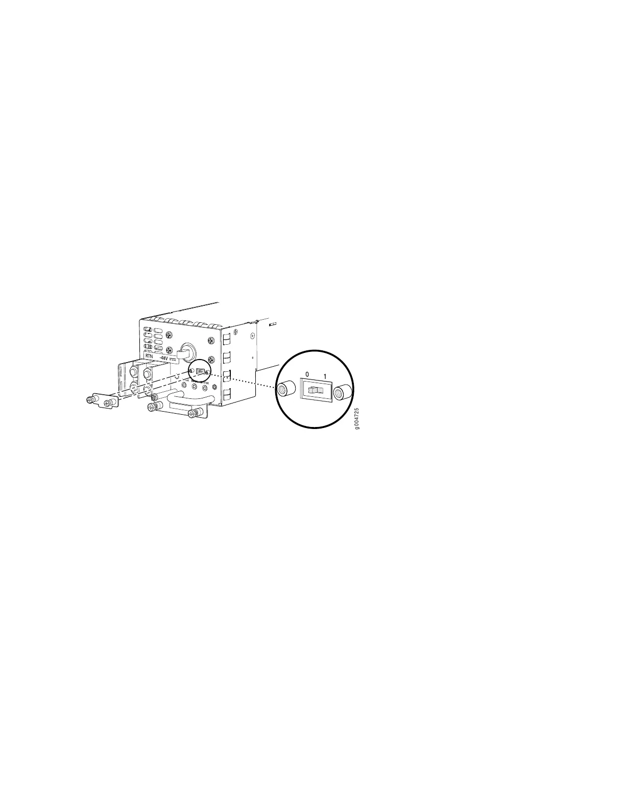
b. Use a sharp, nonconductive object to slide the switch to the desired position. Set the input mode
switch to position 0 for 60-A input and position 1 for 70-A input. This setting is used by the power
management software and must be set on the power supply. See Figure 11 on page 21.
Figure 11: DC Power Supply Input Mode Switch
c. Restore the metal plate to its original position over the input mode switch.
3. Secure the power cable lugs to the terminal studs, first with the split washers, then with the nuts as
shown in Figure 12 on page 22. Apply between 23 lb-in. (2.6 Nm) and 25 lb-in. (2.8 Nm) of torque to
each nut. Do not overtighten the nut. (Use a 7/16-in. torque-controlled driver or socket wrench.)
a. Attach the positive (+) DC source power cable lug to the RTN (return) terminal.
b. Attach the negative (–) DC source power cable lug to the –48V (input) terminal.
21

 Loading...


