Connecting the System
Fusion Catalyst 4000 Getting Started Guide 11
The following boards are Optional:
• Dual or Quad Channel Gigabit Ethernet Board
• Quad HD Decoder Board
• CatalystLink Board
• Sound Board
• RAID 5 Board
Caution Do not use the VGA port. Jupiter Systems does not support
it.
3.2.2 Fusion Catalyst 4000 Cable Connections
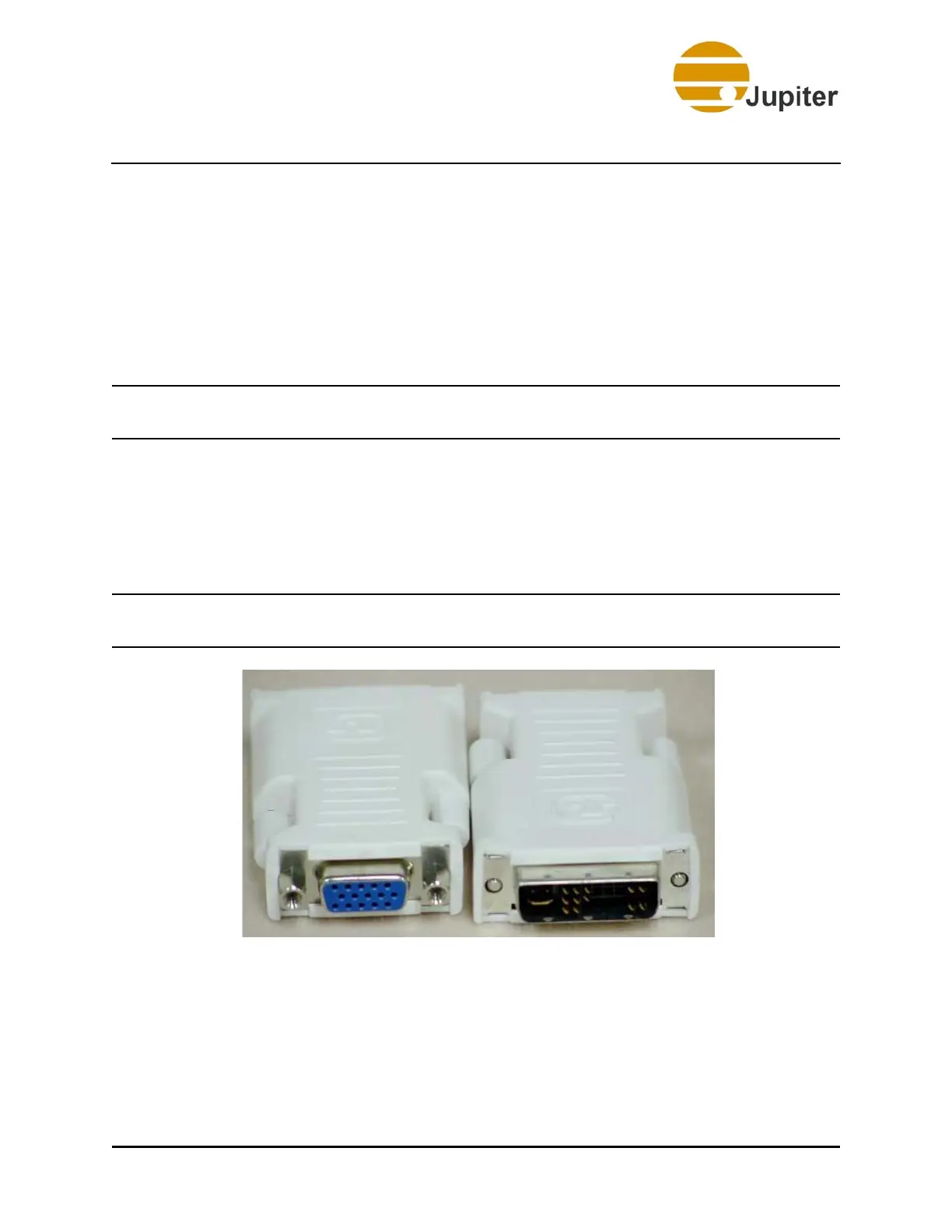
The Catalyst system outputs can be connected with either DVI-D cables or
analog (VGA) cables. If analog cables are used you will need to install the
adapters shown here.
Note Jupiter Systems does not ship the DVI-I to HD 15 Adapters
with Fusion Catalyst 4000.
Figure 4 - DVI-I to HD 15 Adapters
Catalyst output connectors are white. Cables must be connected in output
order. Graphics channels are labeled on the rear of the chassis. Output
channels correspond to display numbering in front view of the wall as
shown in Figure 13 - “Fusion Catalyst 4000 Connection Map” on
page 18.