EasyManua.ls Logo

Jupiter Fusion Catalyst 4000 - Figure 5. DVI Output Connections; Figure 6. DVI-I Input Connections

Jupiter Fusion Catalyst 4000
54 pages
To Next Page IconTo Next Page
To Previous Page IconTo Previous Page
Loading...
3—Hardware Setup
12 Fusion Catalyst 4000 Getting Started Guide
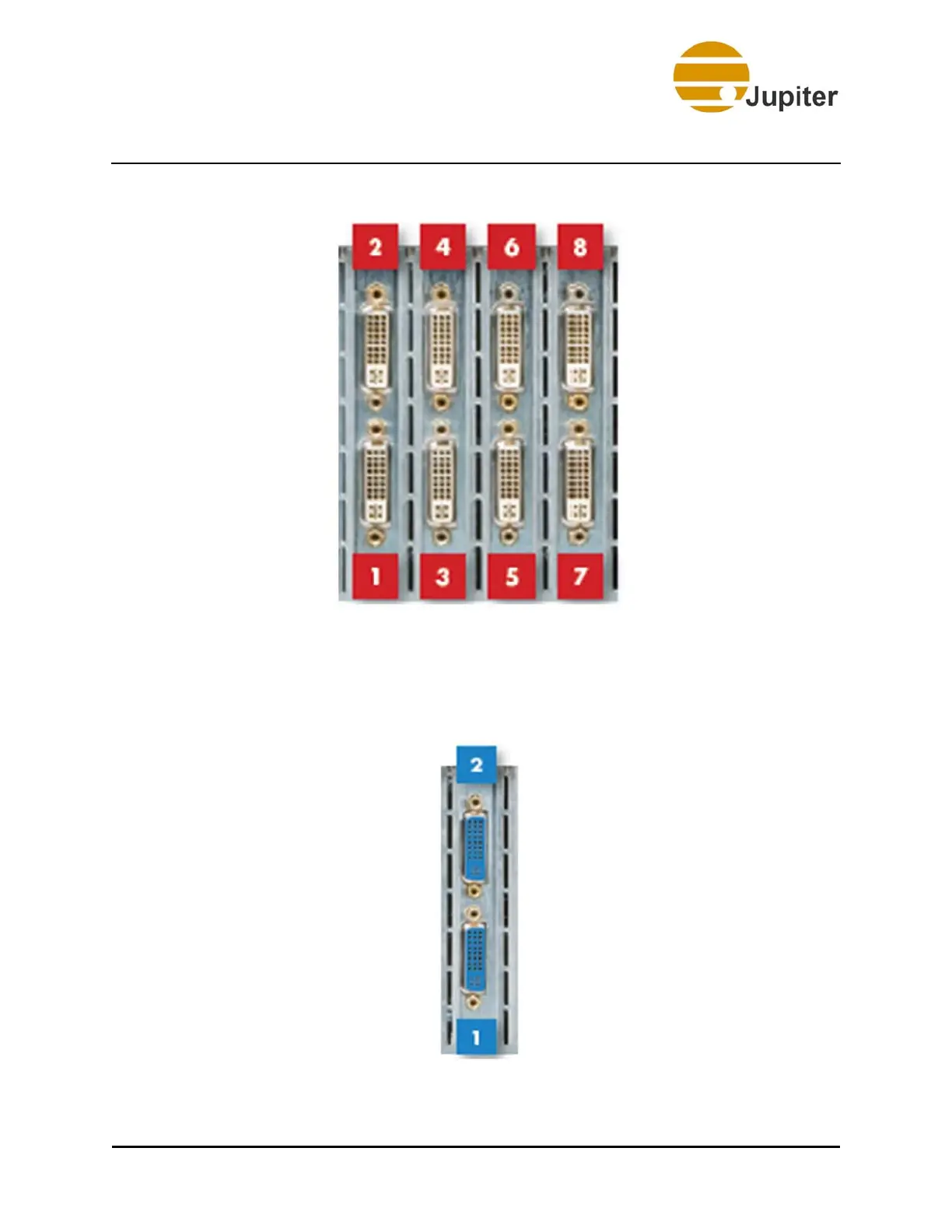
Figure 5 - DVI Output Connections
The Catalyst system DVI input channels are numbered on the rear panel.
These channels correspond to the channel number selected in the
software. DVI input connectors are blue.
Figure 6 - DVI-I Input Connections

Table of Contents

Related product manuals