EasyManua.ls Logo

JVC HR-D540EE - Semiconductors

JVC HR-D540EE
90 pages
Print Icon
To Next Page IconTo Next Page
To Previous Page IconTo Previous Page
Loading...
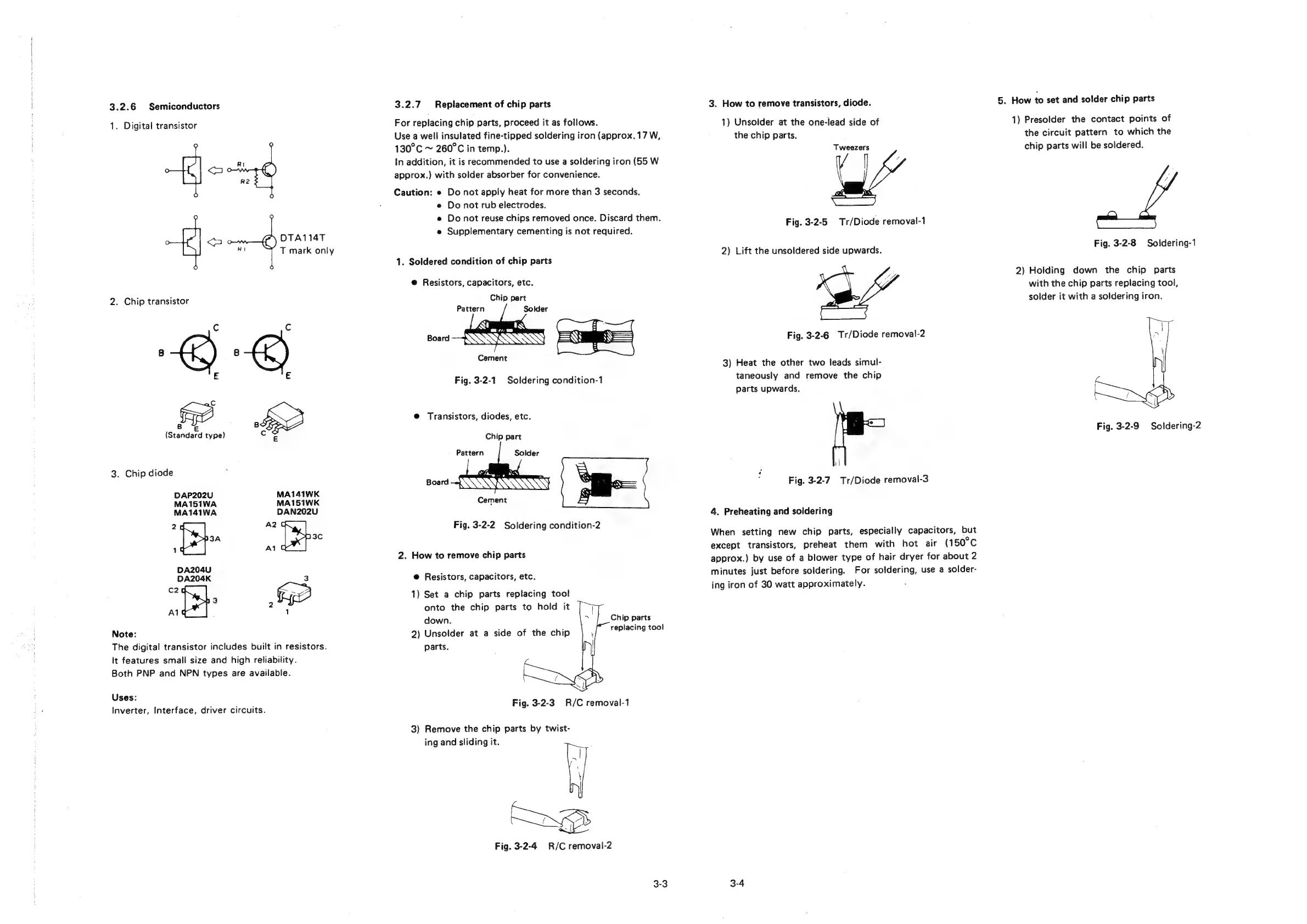
3.2.6
Semiconductors
1.
Digital
transistor
<a
R2
DTA114T
RA
T
mark
only
<
2.
Chip
transistor
Cc
Cc
E
E
Ge
c
E
E
(Standard
type)
3.
Chip
diode
DAP202U
MA141WK
MA151WA
MA151WK
MA141WA
DAN202U
2
A2
3A
3c
1
Al
DA204U
DA204K
3
:
Ge
: 2
Al
;
1
Note:
The
digital
transistor
includes
built
in
resistors.
It
features
small
size
and
high
reliability.
Both
PNP
and
NPN
types
are
available.
Uses:
Inverter,
Interface,
driver
circuits.
3.2.7
Replacement
of
chip
parts
For
replacing
chip
parts,
proceed
it
as
follows.
Use
a
well
insulated
fine-tipped
soldering
iron
(approx.
17
W,
130°C
~
260°C
in
temp.).
In
addition,
it is
recommended
to
use
a
soldering
iron
(55
W
approx.)
with
solder
absorber
for
convenience.
Caution:
e
Do
not
apply
heat
for
more
than
3
seconds.
e
Do
not
rub
electrodes.
e
Do
not
reuse
chips
removed
once.
Discard
them.
e
Supplementary
cementing
is
not
required.
1.
Soldered
condition
of
chip
parts
@
Resistors,
capacitors,
etc.
Chip
part
Pattern
Solder
Cement
Fig.
3-2-1
Soldering
condition-1
@
Transistors,
diodes,
etc.
Chip
part
Pattern
Solder
Board
|
:
Cement
Fig.
3-2-2
Soldering
condition-2
2.
How
to
remove
chip
parts
@
Resistors,
capacitors,
etc.
1)
Set
a
chip
parts
replacing
tool
onto
the
chip
parts
to
hold
it
down.
Chip
parts
2)
Unsolder
at
a
side
of
the
chip
replacing
toe!
parts.
J
Fig.
3-2-3
R/C
removal-1
3)
Remove
the
chip
parts
by
twist-
ing
and
sliding
it.
Fig.
3-2-4
R/C
removal-2
3-3
3.
How
to
remove
transistors,
diode.
1)
Unsolder
at
the
one-iead
side
of
the
chip
parts.
Tweezers
Fig.
3-2-5
Tr/Diode
removal-1
2)
Lift
the
unsoldered
side
upwards.
Fig.
3-2-6
Tr/Diode
removal-2
3)
Heat
the
other
two
leads
simul-
taneously
and
remove
the
chip
parts
upwards.
|
Fig.
3-2-7
Tr/Diode
removal-3
4.
Preheating
and
soldering
When
setting
new
chip
parts,
especially
capacitors,
but
except
transistors,
preheat
them
with
hot
air
(150°C
approx.)
by
use
of
a
blower
type
of
hair
dryer
for
about
2
minutes
just
before
soldering.
For
soldering,
use
a
solder-
ing
iron
of
30
watt
approximately.
3-4
5.
How
to
set
and
solder
chip
parts
1)
Presolder
the
contact
points
of
the
circuit
pattern
to
which
the
chip
parts
will
be
soldered.
Fig.
3-2-8
Soldering-1
2)
Holding
down
the
chip
parts
with
the
chip
parts
replacing
tool,
solder
it
with
a
soldering
iron.
Fig.
3-2-9
Soldering-2