Do you have a question about the JVC RX-230RBK and is the answer not in the manual?
Essential safety guidelines for handling and servicing the product.
Procedure for testing electrical shock hazards after servicing.
Critical warnings regarding maintenance, standards, and safety.
Highlights key capabilities and functionalities of the RX-230RBK receiver.
Explains the manual's purpose, conventions, and how to use it.
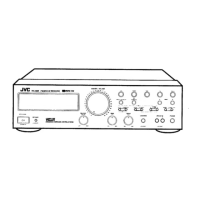
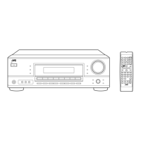
Identifies and describes the main switches and controls on the receiver unit.
Identifies and describes the buttons and functions of the remote control.
Preliminary checks and safety advice before installing the receiver.
Guidelines for optimal placement, spacing, and air circulation.
Instructions for making power connections and handling cords safely.
Verifying that all necessary accessories are included with the unit.
Guidance on connecting various audio components using RCA cables.
How to connect JVC audio components for integrated control.
Steps for connecting speaker wires to the receiver terminals, including polarity.
Instructions for connecting AM/MW/LW and FM antennas for optimal reception.
How to turn the receiver on, standby, and completely off using switches.
Steps for inserting batteries into the remote control for operation.
How to choose input sources like CD, PHONO, TAPE, FM, AM.
Using TAPE 2/VIDEO SOUND button for recording quality checks.
Using master volume controls on the unit and remote for sound level.
Adjusting bass, treble, and left-right balance for audio output.
Boosts bass at low volumes to compensate for hearing sensitivity.
Creates a movie-theater effect by engaging the surround sound feature.
Allows the receiver to turn off automatically after a set time.
How to tune AM, MW, LW, and FM stations using manual or auto methods.
Selecting FM stereo/mono modes to optimize reception quality.
Storing favorite radio stations into memory channels for quick access.
How to recall stored stations using front panel or remote buttons.
Utilizing RDS features to display station names and program types.
Locating specific program types by using PTY codes.
Allows temporary switching to other broadcast programs like NEWS or TA.
How to activate, use, and deactivate the EON standby mode for program switching.
Operating connected JVC components remotely via the receiver's control.
Receiver automatically switches to component when play is pressed.
Setting up automatic recording between components for convenience.
Components turn on/off automatically with the receiver.
A guide to diagnose and resolve common operational issues with the receiver.
Technical data for the amplifier section, including power output and frequency response.
Technical data for FM, MW, and LW tuners, including sensitivity and tuning range.
Procedures for adjusting tuning voltage and FM center meter settings.
Steps for setting and adjusting the idling current for the amplifier.
Illustrates the path of audio signals through the receiver's main sections.
Shows the interconnected control circuits and ICs within the receiver.
Diagram of the power supply circuitry and voltage regulation.
Detailed circuit diagram for the power amplifier stage of the receiver.
Visual layout of components on the tuner circuit board (ENA-167).
An exploded diagram showing component locations and a list of parts.
Detailed listing of all electrical components, their numbers, and descriptions.
List of accessories provided with the receiver, including manuals and cables.
Details on how the unit is packed for shipping and included materials.
| Power output | 40 watts per channel (6 ohms, 1 kHz, 10% THD) |
|---|---|
| Total harmonic distortion | 0.7% (1 kHz, 1 watt) |
| Dimensions | 420 x 145 x 330 mm (W x H x D) |
| Weight | 4.1 kg |
| Tuning range | FM: 87.5 - 108 MHz |
| Frequency response | 20Hz to 20kHz |
| Input sensitivity | 200 mV |
| Speaker load impedance | 6 - 16 ohms |
| Input Sensitivity/Impedance | 200 mV (line) |
| Signal-to-Noise Ratio | 100 dB |
| Speaker Impedance | 6 ohms |