Design and Function
4 --- 22
4.1.2 Function
An air–cooled machine serves to illustrate function.
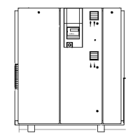
Fig. 3 Air---cooled machine
1 Inlet valve 6 Control cabinet
2 Minimum pressure/check valve 7 Oil separator tank
3 Compressor motor 8 Air filter
4 Oil filter 9 Oil / air cooler
5 Airend
Machine
Ambient air is cleaned as it is drawn in through the filter (8).
The air is then compressed in the airend (5).
The airend is driven by an electric motor (3).
Cooling oil is injected into the airend. It lubricates moving parts and forms a seal between
the rotors themselves and between them and the airend casing. The cooling effect directly
within the compression chamber ensures a low airend discharge temperature.
Cooling oil recovered from the compressed air in the oil separator tank (7) gives up its heat
in the oil cooler (9). The oil then flows through the filter (4) and back to the point of injec-
tion. Pressure within the machine keeps the oil circulating. A separate pump is not necess-
ary. A thermostatic valve maintains optimum oil temperature.
Compressed air, freed of its oil content in the separator tank (7), flows through the mini-
mum pressure/check valve (2) into the aftercooler (9). The minimum pressure/check valve
ensures there is always sufficient internal pressure to maintain cooling oil circulation.
The aftercooler brings down the compressed air temperature to 5 to 10 K above ambient.
Most of the moisture carried in the air is removed in the aftercooler.
4.1.3 Volt---free Contacts
Volt---free contacts are provided for passing messages.
Information on location, load and type of message is to be found in the electrical diagram.
If the volt---free contacts are connected to an external power source they
may be under power even when the machine is isolated from the supply.
 Loading...