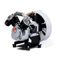
Do you have a question about the KAESER EPC Series and is the answer not in the manual?
Instructions on how to use and maintain the service manual throughout the machine's life.
Lists additional documents included with the service manual for safe machine operation.
States that the service manual is copyright protected and directs queries to KAESER.
Details symbols for important information, material, preconditions, options, and further topics.
Details on machine identification and technical information found on the nameplate.
Lists and describes available optional equipment for the machine, with option codes.
Information on the weight of the machine and its components.
Specifications related to the compressor block, including displacement and cylinder count.
Specifies permissible ambient temperature and altitude for operation.
Provides minimum guide values for inlet aperture and exhaust fan capacity.
Details the factory settings for cut-in, cut-out, and differential pressure.
Specifies activating pressures for various relief valves on the machine.
Presents sound pressure levels for different machine models under operating conditions.
Details motor power, speed, and degree of protection ratings.
Recommends specific oils for the compressor and provides oil change intervals.
Covers basic requirements and specifications for three-phase power supply connections.
Outlines network impedance requirements for machine operation with public power supply.
Explains how to calculate duty cycle and provides valid values for ambient conditions.
Provides an overview of the machine and identifies its main components.
Explains how the machine draws in, compresses, and delivers air.
Details the function of the oil level monitoring system and automatic shutdown.
Describes the 'pressure low' warning system for control centre notifications.
Explains the purpose and function of adjustable machine mountings.
Details the benefits of the silenced air filter for noise reduction and air cleaning.
Describes the air filter suitable for unfavorable ambient conditions.
Explains the automatic removal of condensate from the air receiver.
Details the solenoid valve controlled condensate drain system.
Describes the function of the pressure regulator in reducing and stabilizing discharge pressure.
Describes the operational states (LOAD, STANDSTILL) and control mechanisms.
Details the provided safety devices and emphasizes that they must not be modified.
General safety precautions related to installation, fire, and explosion protection.
Covers requirements for location, clearances, ventilation, and network connection.
Provides recommendations for machine placement and necessary clearances.
Explains the importance of ventilation and requirements for air flow.
Addresses considerations when connecting the machine to a compressed air network.
Instructions for safe initial start-up and working on machine components.
Procedure for checking and reporting any damage incurred during transport.
Guidance on correctly installing vibration-dampening mounts for the machine.
Instructions for connecting the machine to the compressed air system.
Details on safely connecting the machine to the power supply by authorized personnel.
Details the oil level monitor option and its connection and setting adjustments.
Instructions for securing the machine using adjustable mounting points.
Guidance on fitting the ECO-DRAIN automatic condensate drain.
Explains how to install and set the pressure regulator with filter.
Safety instructions for initial start-up and working on live components or pressure systems.
Highlights the importance of correct initial start-up to prevent machine damage.
Checklist of items to confirm before the first start-up of the machine.
Details on the importance and setting of the motor overload protection switch.
Procedure for checking and correcting the machine's direction of rotation.
Steps for safely starting the machine for the first time and checks after initial operation.
Method for measuring air receiver charging time to check machine performance.
Instructions on adjusting the network working pressure to suit operating conditions.
Guidance on adjusting the filter regulator unit to maintain constant working pressure.
General information on alarm indications and fault rectification measures.
Lists common faults, their possible causes, and suggested remedies.
Safety instructions for performing maintenance work on the machine.
Guidelines for logging maintenance work and recommended intervals for tasks.
Procedure for cleaning the air cooler or fan guard to prevent overheating.
Instructions for maintaining the air filter insert made of fibre mesh.
Details on the maintenance of the noise-absorbing air filter element.
Describes the maintenance of the air filter with a plastic casing.
Information regarding drive motor bearings, which require no re-greasing.
Procedure for checking the oil level using the oil sight glass.
Instructions on how to safely top up the compressor oil, avoiding mixing types.
Steps for draining and refilling the compressor oil.
Guidance on testing pressure relief valves to prevent sticking and ensure safety.
Instructions for inspecting the air receiver and draining condensate.
Procedure for safely venting the machine (de-pressurising) before maintenance.
Details on maintaining the check valve located at the air receiver inlet port.
Instructions for isolating the machine and venting before solenoid valve maintenance.
Describes checking and maintaining the ECO-Drain automatic condensate drain.
Instructions for cleaning or changing solenoid valves.
Procedure for cleaning the filter element in the pressure reducer unit.
Guidance on checking, cleaning cylinder head and valves, and tightening torques.
Template for logging maintenance and service tasks performed on the machine.
Emphasizes the importance of the nameplate for identifying the machine and ordering spares.
Guidance on ordering original KAESER parts and materials, and warnings about unsuitable products.
Highlights the benefits of KAESER AIR SERVICE for maintenance and operational reliability.
Indicates that KAESER agent addresses are provided at the end of the manual.
Advises that tasks not described in the manual should be done by an authorized technician.
Procedures for temporary and long-term de-commissioning of the machine.
Advice on packing the machine for overland, sea, or air transport.
Precautions for storing the machine to prevent damage from moisture and frost.
Safety guidelines and methods for transporting the machine using forklifts or cranes.
Instructions for the proper disposal of the machine and its components.
Provides the P+I diagram for the two-stage EPC unit.
Presents dimensional drawings and specifications for various machine configurations.
Contains electrical diagrams for the machine, including circuit and component layouts.
| Type | Rotary Screw Compressor |
|---|---|
| Drive Type | Direct Drive |
| Cooling System | Air-cooled |
| Control System | Sigma Control 2.0 |
| Weight | Varies depending on model |
| Noise Level | 62 - 75 dB(A) (depending on model) |


