4.1.2 Machine function
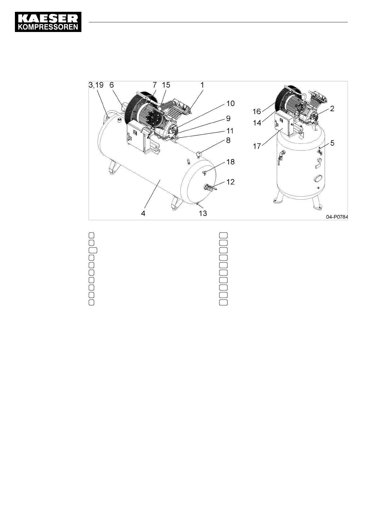
Fig. 3 Machine layout
1 Air filter
2 Compressor block
2a 2-cylinder block
3 Check valve
4 Air receiver
5 Air receiver pressure relief valve
6 Pressure switch
7 Electric motor
8 Pressure gauge
9 Oil sight glass
10 Oil filler port
11 Oil drain plug
12 Compressed air connection
13 Condensate drain tap
14 Arrow showing direction of rotation
15 Cylinder or collecting pipe relief valve
16 Air cooler
17 Star-delta starter
18 Test flange
19 Solenoid valve
Machine
Atmospheric air is drawn through a filter into the compression chamber of the block. The air is drawn
in during the downward stroke of the piston. It is compressed during the upward stroke.
The compressed air flows through the cooler, giving up most of its heat, then via the check valve into
the air receiver. The check valve prevents reverse flow of compressed air from the air receiver to the
compressor block.
4.2 Options
The options available for your machine are described below.
4.2.1 Option C5
Oil level monitoring
The oil level in the machine is monitored automatically. The machine is automatically shut down if the
oil level falls below minimum.
4 Design and Function
4.2 Options
22
Service Manual 2-stage piston compressor
EPC No.: 9_9431_02 E

 Loading...


