Do you have a question about the KAESER M27 and is the answer not in the manual?
Instructions on how to use the operating manual, its importance, and how to maintain it.
Lists additional documents included with the operator manual for comprehensive information.
States that the operator manual is copyright protected and directs queries to KAESER.
Explains the importance of noting symbols and labels used throughout the document.
Describes the machine's nameplate and its purpose for identifying technical information.
Lists and explains various options fitted to the machine, identified by code letters.
Provides fundamental safety instructions for operating the machine and highlights potential dangers.
Defines the intended use of the machine and warns against incorrect usage.
Details the consequences of improper usage, including property damage and injuries.
Outlines the responsibilities of the user, including adhering to regulations and determining personnel.
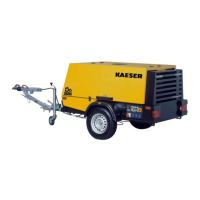
Describes the exterior of the machine and its functions when closed, such as weather and sound protection.
Identifies and labels the various components of the machine with a visual diagram.
Explains the basic function of the machine without options and refers to flow diagrams.
Details the different operating modes (LOAD, MODULATING, IDLE, STANDSTILL) and control modes.
Highlights safety considerations during machine installation and operation, emphasizing warning compliance.
Specifies necessary conditions for installation, including floor requirements and ambient conditions.
Provides instructions for safe installation, referencing safety chapters and authorized personnel.
Instructs on how to check for and report any transport damage found on the machine.
Details the process of fitting the towbar to the machine, including material and preconditions.
Outlines safety measures for commissioning the machine, emphasizing authorized personnel and locked panels.
Provides instructions to be observed before initial startup or recommissioning.
Presents a checklist for verifying installation and operating conditions before starting the machine.
Details specific operating materials and procedures for starting and running the machine in cold temperatures.
Provides safety instructions for machine operation, covering general safety and specific hazards.
Explains the procedure for starting and stopping the machine, including instrument panel functions.
Details the procedure for operating the tool lubricator, including checking oil level and setting oil flow.
Describes the operation of low-temperature equipment, including coolant pre-heating and frost protection.
Provides basic guidelines for fault finding and rectification, and when to contact KAESER Service.
Details common engine faults, their possible causes, remedies, and where to get help.
Lists compressor faults, their causes, remedies, and recommended support channels.
Covers faults and alarms related to the generator, including voltage issues and engine speed.
Emphasizes safety precautions required for performing maintenance tasks on the machine.
Provides recommended maintenance intervals and tasks for the machine and its components.
Details specific maintenance procedures for the engine, including coolant, filters, and oil.
Outlines maintenance tasks for the compressor system, including oil, filters, and safety valves.
Explains the importance of the nameplate for identifying the machine and ordering spares.
Provides guidance on ordering original KAESER consumable parts and operating fluids.
Describes the services offered by KAESER AIR SERVICE for machine maintenance and reliability.
Indicates where to find addresses of KAESER representatives at the end of the manual.
Covers procedures for temporary and long-term decommissioning and storage of the machine.
Provides detailed instructions for safely transporting the machine, including coupling and securing.
Offers guidance on storing the machine to prevent corrosion and damage from moisture and frost.
Explains the procedures for decommissioning and disposing of the machine and its fluids.
Explains how to identify the machine using VIN, options label, and manufacturer/engine nameplates.
Provides detailed pipeline and instrument flow diagrams for understanding the machine's systems.
Contains dimensional drawings of the machine with various chassis options for reference.
Includes electrical diagrams and wiring schematics for different machine configurations and options.
| Brand | KAESER |
|---|---|
| Model | M27 |
| Category | Air Compressor |
| Language | English |