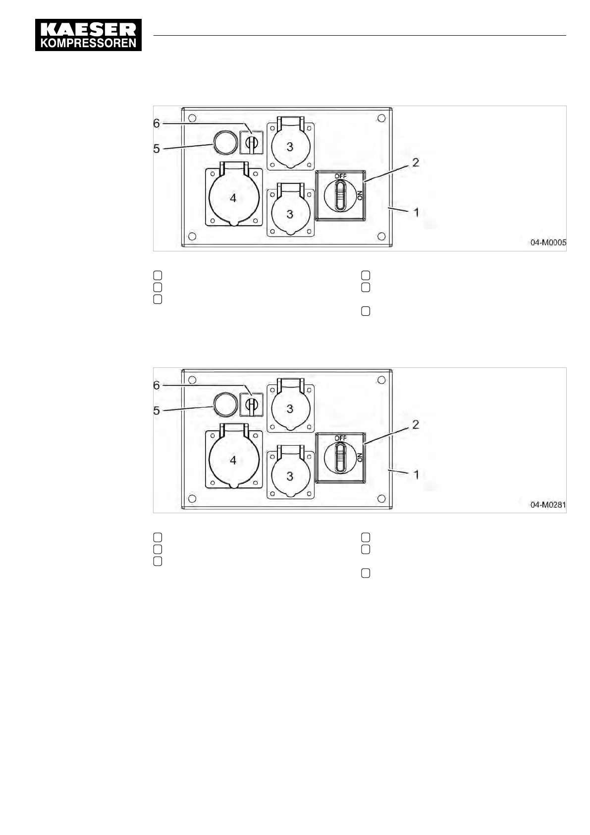
Fig. 8 Instrument panel, generator control box 400 V/3~/N/PE, 50 Hz
1 Generator control box
2 «Generator main switch»
3 Power socket 230 V/1~/N/PE, 50 Hz
4 Power socket 400 V/3~/N/PE, 50 Hz
5 Test button «insulation monitor» with indi‐
cator light for ground short
6 «Mode selector switch»
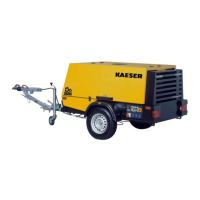
Generator control box 115V
Sockets and switches 115 V/1~/N/PE, 50 Hz, 32 A generator, see illustration
9.
Fig. 9 Instrument panel, generator control box 115 V/1~/N/PE, 50 Hz, 32 A
1 Generator control box
2 «Generator main switch»
3 Power socket 115 V/1~/N/PE, 50 Hz, 16 A
4 Power socket 115 V/1~/N/PE, 50 Hz, 32 A
5 Test button «insulation monitor» with indi‐
cator light for ground short
6 «Mode selector switch»
4.6.3 Option ba
Low temperature equipment options
The machine is fitted with low-temperature equipment for the operation in extremely low tempera‐
tures.
This equipment guarantees machine operation at ambient temperatures from -13°F to 113°F.
The electrical system enables trouble-free engine starting at ambient temperatures down to -4°F.
4 Design and Function
4.6 Options
No.: 9_9548 05 USE
Operator Manual Screw Compressor
M27
45