7.5.2 Generator control box 115V with insulation monitoring
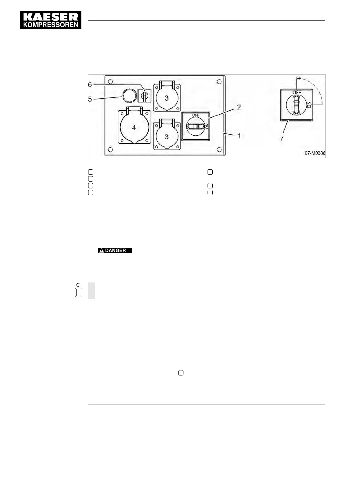
Fig. 30 Insulation monitoring - 115V, single-phase generator
1 Generator control box
2 «Main switch»
3 Single phase AC power socket, 16 A
4 Single phase AC power socket, 32 A
5 Test button «insulation monitor» with indi‐
cator light for ground short
6 «Mode selector switch»
7 Position «main switch» after the main cir‐
cuit breaker has been activated
➤ Please note the positions of «insulation monitor» and «main switch» test buttons.
7.5.3 Testing the insulation monitor
1. Activate the machine
2.
Danger of fatal injury caused by contact with live components!
➤ The generator may only be used if the «circuit breaker» («main circuit breaker») has trip‐
ped during the test!
3. Check the insulation monitor according to instructions:
Test instructions are provided on the label attached to the generator control box.
DANGER!
Electrical power
Danger of fatal injury caused by contact with live components!
▶ Test the «main circuit breaker» each day while the machine is running.
▶ The generator may only be operated if the main circuit breaker is functioning correctly.
Checking the «safety cut-out»:
➤ Turn on the «main circuit breaker» for the generator.
➤ Press and hold the «test button» 5 for 3 seconds.
The «main circuit breaker» trips.
Problem: The «main circuit breaker » does not trip?
➤ Shut down the generator and call an authorized KAESER service representative.
Tab. 67 Test instructions for a generator with a ground short detection device
7 Initial Start-up
7.5 Activating the generator
No.: 9_9548 05 USE
Operator Manual Screw Compressor
M27
81