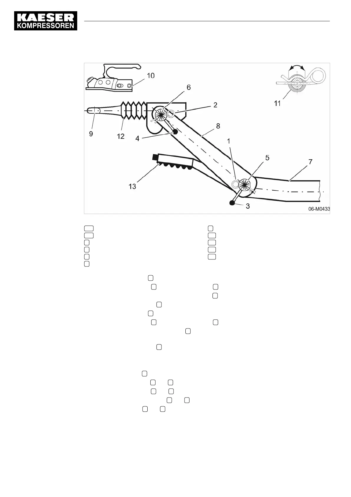
Fig. 19 Towbar height adjustment rb/rm/rs
1,2 Split pin
3,4 Locking lever
5 Serrated joint 1
6 Serrated joint 2
7 Towbar tube
8 Towbar adapter
9 Towing eye
10 Ball coupling
11 Split pin (securing principle)
12 Overrun damper
13 Parking brake
1. Draw out the split pin 1 .
2.
Undo the locking lever 3
until the serrated joint 5 is disengaged.
3.
Make the angle adjustment to the serrated joint 5
.
4.
Tighten the locking lever 3
making sure the serrations engage.
5.
Draw out the split pin 2
.
6.
Undo the locking lever 4
until the serrated joint 6 is disengaged.
7.
Adjust the angle of the serrated joint 6
to bring the towing eye or coupling parallel to the
ground at the height of the towing vehicle hitch.
8.
Tighten the locking lever 4
making sure the serrations engage.
9.
Check that the tow bar is adjusted to the correct height.
Check if:
■ the towing eye 9
or coupling is at the right height and parallel to the ground,
■
the serrated joints 5
and 6 are fully engaged,
■
The locking levers 3
and 4 are tightened.
10.
Make sure the locking levers 3
and 4 are tight by striking with a hard rubber hammer.
11.
Insert the split pins 1
and 2 .
6 Installation
6.4 Adjusting the chassis
62
Operator Manual Screw Compressor
M27 No.: 9_9548 05 USE