9.10 Structure and mounting of the
cab
9.10.1 Cab mounting and suspension
Adjust the cab air suspension
1 Park the vehicle on firm level ground.
2 Start and run the engine until the air system has a minimum of
100 psi of air pressure.
3 Stop the engine.
4 Turn on (open) the air supply to the cab suspension by turning
the “T-handle” valve on the bottom of the deck counterclock‐
wise.
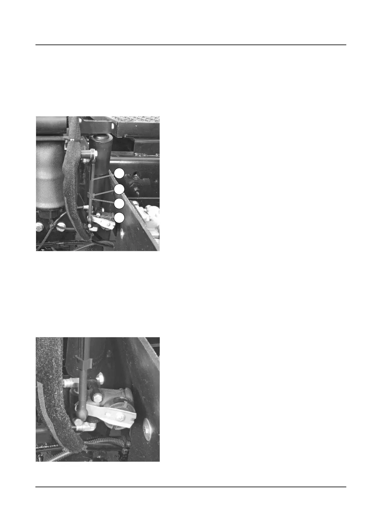
5 Remove the plastic clip (B) in the center of the plastic linkage
rod connected to the control arm on the suspension assem‐
bly.
6 Use tape to mark the linkage rod's current position (C).
7 Adjust the linkage rod length as required to set proper ride
height. Disengage the serrated lower end (D) of the rod from
the serrated portion of its upper sleeve (A):
•
To raise ride level — Decrease the rod (D) length by
placing the rod deeper into the upper sleeve (A).
•
To lower ride level — Increase the rod length by reducing
the insertion of the rod in the sleeve.
NOTE
One inch (25.4 mm) of clearance is required between the stop bump‐
ers on the air suspension assembly and the channel at the bottom of
the cab deck for proper ride height.
Examine the leveling valve operation
Examine for proper operation of the leveling valve as follows:
1 While holding the cab entry handle in the “DOWN” position,
count the time in seconds it takes for the air spring to raise the
ride height.
2 If the noted time is:
•
Within 2–10 seconds — Valve is OK.
•
Under 2 seconds— Valve is damaged or filter is clogged.
•
Over 10 seconds — Valve is damaged or filter is clog‐
ged.
3 Replace the valve if the valve is damaged or the filter is clog‐
ged.
9 Frame, body, cab and accessories – 9.10 Structure and mounting of the cab 7
TL2 Maintenance Manual
591 003 Default